Hello,
Sorry for this silly question, but I have to admit that I can't figure it out.
I use a sensor powered by 3V3 which has two analog outputs. These outputs have a reference which equals VDD/2 with respect to ground. I will call this reference the "negative" pole.
These two analog outputs can therefore vary from -1V25 to +1V25.
I was think easy for me to connect it to the ADC ADS124S06. I connected the negative pole to the AINCOM input and the + poles to AIN0 and AIN1. I use as an external reference the 3V3.
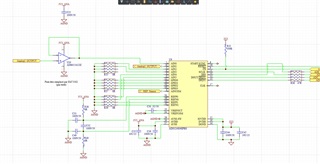
For information, here is the schema of this part.

In the software I have configured the following registers:
DATARATE: 0x38 //configure 200SPS, low-latency filter, single shot
REF: 0x30 //configure REFP_BUF and REFN_BUF disabled
VBIAS: 0x00
PGA: 0xC8 //configure PGA enabled, conversion delay 4096*tMOD
For my test in the INPMUX register: AINCOM is configured as negative input and AIN1 as positive input
The others registers are left with the original values.
I don't know what I did wrong, but it doesn't work properly.
To do a test I use a lab power supply where I place AINCOM on the - terminal and AIN1 on the + terminal. What is strange in this configuration the value of the ADC remains constantly close to value. If I place AINCOM on the + terminal and AIN1 on the - terminal, that gives me a correct negative value and I can go up to 3V25?!
If I change the PGA configuration to 0xC0 (PGA bypassed):
To do a test I use a lab power supply where I place AINCOM on the - terminal and AIN1 on the + terminal. In this configuration the ADC value is correct up to around 0V3 with a positive value, beyond that the value is no longer correct. If I place AINCOM on the + terminal and AIN1 on the - terminal, that gives me a correct negative value and I can go as far as 3V3?!
Can you give me some clues please?
THANKS.

