Hi,
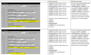
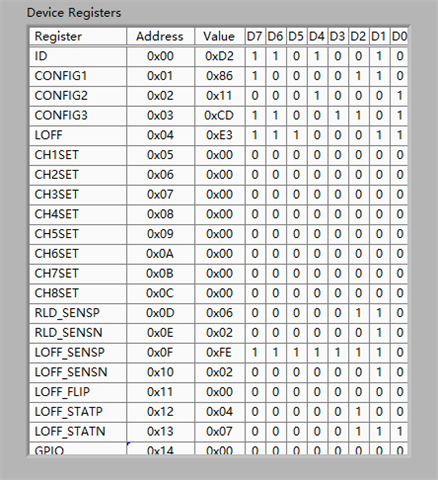
I made the following test with ADS1298REVM. The registers are shown below.
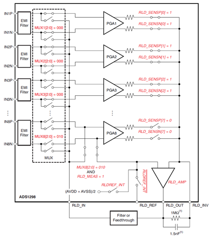
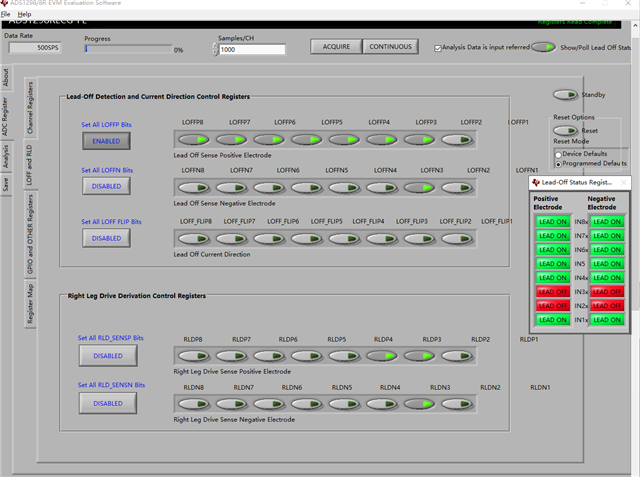
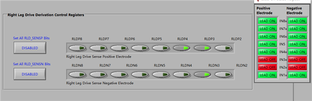
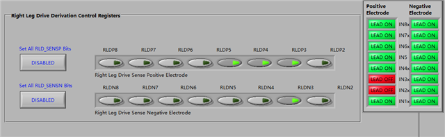
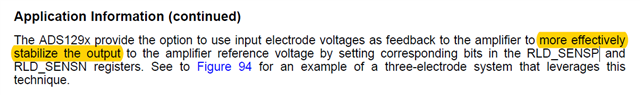
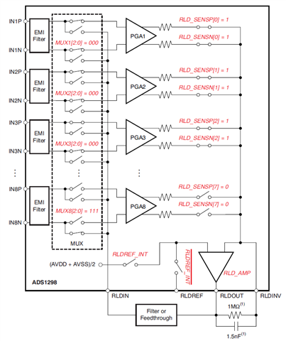
The RLD is set as (LA+RA+LL)/3. LOFFP/LOFFN and RLD_SENSP/RLD_SENSN are shown below.
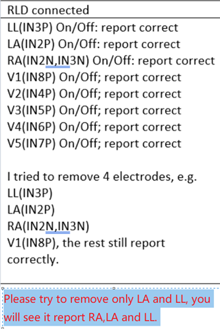
Question1. When the LL lead is take off, the register shows that the LL and RA are both off. Can you help to solve this problem?
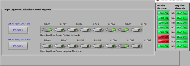
Question2. I find that when I set RLD=(LA+RA+LL+V1+V2+V3+V4+V5)/8. The above problem will be solved.
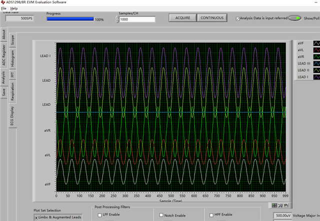
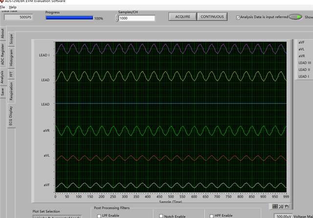
But that makes the waveform changes. What is the right RLD configuration?
When RLD=(LA+RA+LL)/3
When RLD=RLD=(LA+RA+LL+V1+V2+V3+V4+V5)/8
Thank you.
Frank