This thread has been locked.

If you have a related question, please click the "Ask a related question" button in the top right corner. The newly created question will be automatically linked to this question.

Amplifier and A/D for Load Cell

Other Parts Discussed in Thread: INA128, PGA308, MSP430F5659, INA851, ADS8168, ADS8860, OPA320, PGA309, INA849

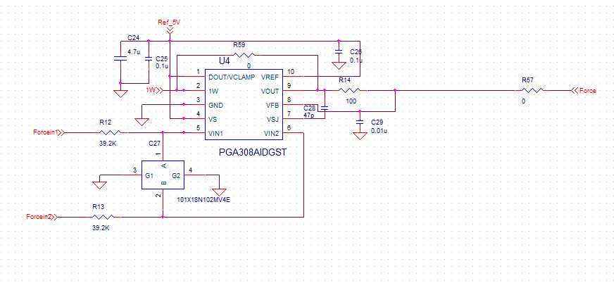
I am designing a load cell amplifier. The load cell output/amplifier input is 2mv/v, and the amplifier's output is 3V. I need an A/D's sampling speed to be 200k-500k.

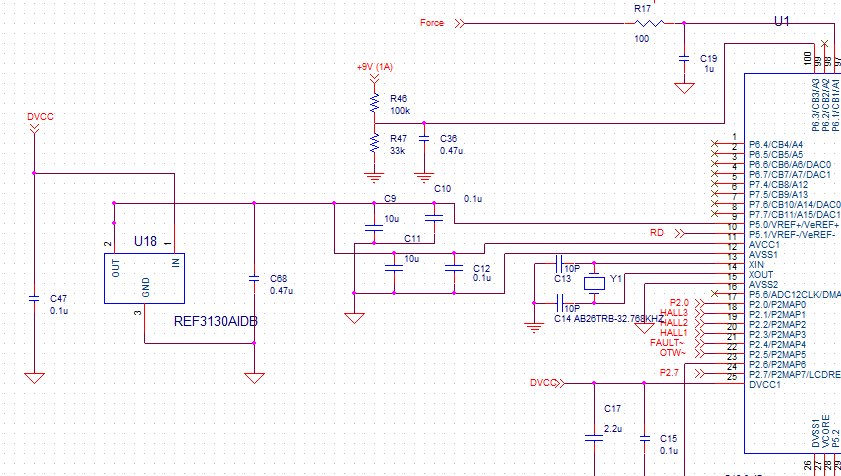
Would the INA128 be OK? if not please recommend a better amplifier and A/D. Currently I'm using a PGA308 for the amplifier, and the MSP430F5659's built in 12Bit A/D for the A/D, but the repeatability is too low, varying by +/-3-4 LSB. I believe a more precise A/D, such as a 16bit one, will contribute to better repeatability, as well as a faster amplifier.

  • Shawn,

    1. Regarding the sampling rate of your ADC and your amplifier bandwidth:  Do you expect to see sensor variations between 200k to 500k?  In other words, do you need an amplifier bandwidth greater than or equal to 500k?  Or, alternatively, are you collecting at this rate to do oversampling / averaging?  
    2. The ability of an amplifier to drive an ADC at a given sample rate depends on the ADC type and design.  For example, some ADC include an integrated buffer or PGA (typically Delta-Sigma).  Other ADC (typically SAR), may require a fast amplifier to drive the internal sample and hold.  Can you specify which ADC you are using?  
    3. This is probably less than you want.  This document shows an example of direct drive of a SAR with an INA (https://www.ti.com/lit/an/sbaa245a/sbaa245a.pdf?ts=1686154429443 ).  One challenge to consider is you INA supply voltages.  What supply voltages are you planning on using for the INA?  Most of the INA are optimized for a wider supply voltage.  This document shows how to protect the input if a different supply is used than the ADC input range.
    4. Based on your post, I think you need a gain of 500.    Gain = Vout/Vin = Vout/(Vexe*Vsen).  Vexe is the load cell excitation voltage.  Assuming the excitation voltage is 3V, the gain is : Gain = 3V/(3V*2mV/V) = 500.  Using the INA128 give a bandwidth of about 50kHz (from simulation).  
    5. Options for driving a SAR include using a buffer amplifier (or an amplifier in gain to partition the gain and get more bandwidth out of your INA).  This is a common approach (see https://www.ti.com/lit/an/sbaa277a/sbaa277a.pdf?ts=1686154387519 ).
    6. Options for INA include wider bandwidth options like INA851.  This device is designed for driving a differential ADC input.  This device includes features like integrated clamps to solve the problem where the INA supply and ADC input range are different.
    7. The PGA308 is designed to be calibrated.  Once calibrated the output will be very accurate. If you are not doing a calibration procedure this isn't a good option as the inherent accuracy isn't great.  However, if you are doing calibration, the post calibration accuracy should be better than 0.1%.  I can help with the PGA308 if you want to continue to pursue this option.  

    Sorry for all the questions, but I need a little more info to fully help you out.

    Best regards, Art

  • Art, thank you for getting back to me.

    1. This is a closed loop feedback system, where we are continuously sampling the signal from a force load cell, and adjusting the motor to increase or decrease the force in real time. We need to sample at minimum 200k, and are currently averaging two samples for each point. We probably won't need to go over 500K bandwidth.

    2. Right now, I'm using the A/D built into the MSP430F5659 microcontroller. It's 12 bits, so I'm wondering if changing to a standalone A/D with a higher precision would improve the repeatability.

    3. Right now, I'm using 5V for the PGA308. I can increase it up to +/-15V if necessary.

    4. You're right, the gain needs to be at least 500, so the INA128's bandwidth is too low.

    5 & 6. Thanks for the design tips. I'll check them out.

    7. The easiest and preferred solution is to just tweak the existing PGA308 design. I have been calibrating it, but I can't seem to get the error down to 0.1%. Right now, it's around 0.3 - 0.4%. I am wondering if a tweak to the design will solve the repeatability problem. I attached my PGA308 design, and how it feeds into the microcontroller's A/D. Would it be possible to get the accuracy to be better than 0.05%?

    Thank you!

  • Hi Shawn,

    Just to jump in on Art's comments, the ADC12 found in the MSP430F5659 has total unadjusted error of ~ 4-5 bits.  Can you increase your sample average to 4 or even 8?  That should improve the results as well.

  • Tom,

    Thanks for that extra detail.  

    Shawn,

    1. I don't know a lot about the MSP430 built in ADC.  The main key thing that the ADC will need is that the result needs to be low noise, low drift, and linear.  If it has a gain and offset error, that can be calibrated out at the same time you calibrate the PGA308 and sensor errors.  
    2. The ADC team has a wide range of stand alone ADC that would work well with the PGA308.  A good choice is the ADS8860 (16 bit precision SAR), or ADS8168 (basically and 8 channel version of the ADS8860).  There are many options and Tom could help you with that.
    3. Regarding the PGA308.  I'm not sure that the bandwidth will meet your needs.  The bandwidth of the input is 400kHz in a gain of 4V/V, and the gain bandwidth product of the output amplifier is 2MHz.  You need a gain of at least 500, so a typical partitioning of gain would be Gin = 100, Gout = 5.  There is not simple formula for bandwidth on the input stage, but based on figure 12 I think it is probably close to 100kHz.  In a gain of 5 the output stage bandwidth is 400kHz.  So the PGA308 may have sufficient bandwidth but I think this is something we should double check.
    4. One solution, that can help with the PGA308 bandwidth issue is to add a post amplifier.  You could put the post amplifier in a gain of 2 or 3, and this will allow lower gain on the PGA308 so that the bandwidth is higher.   The post amplifier can also be an amplifier that is optimized for driving a SAR converter like OPA320.
    5. Regarding the post calibration accuracy of the PGA308.  It is typically significantly better than 0.1% (e.g. 0.05% or better).  However, temperature drift, and sensor drift will make that change.  Normally load cells will have temperature drift and pressure non-linearity.  Are you correcting or compensating for that?  If not that may be the source of your error.
    6. The calibration procedure for the PGA308 is similar to PGA309.  That is given here: PGA309_calibration_procedure (3).pdf
    7. I looked at your schematic.  One possible issue is the RC on the input of the ADC (100 ohm x 1uF).  This limits your frequency to 1.59kHz.  It also is a capacitive load for the PGA309.  Capacitive loads make amplifiers unstable. The 100 ohm resistor helps to isolate the capacitance but still may not be enough to keep the PGA309 stable.  When an amplifier is unstable it oscillates.  I would need some time to know what capacitance and isolation resistor would work for PGA309, but the one you are using doesn't make sense as it doesn't even come close to your bandwidth requirement.
    8. Perhaps to simplify things, you might consider switching to a different INA.  The main advantage of the PGA308 is that you can program it up so that it acts as a sensor in and calibrated voltage out amplifier.  In your case you are using an ADC and will need to calibrate anyhow.  The INA849 is a wide bandwidth INA.  In a gain of 1000V/V it still has 1.25MHz of bandwidth.  This device does require wider supplies so you should probably do something like: www.ti.com/.../sbaa277a.pdf.  I think this is a relatively simple option, and perhaps your best option.  You could use a https://www.ti.com/tool/DIP-ADAPTER-EVM to prototype a connection into our existing design and see if you get better performance.

    That is a lot of information!  I hope it helps.  Once you decide on a path you would like to peruse I can help you with the details.  

    Best regards, 

    Art Kay

  • Art,

        Thanks for all the information! Regarding point 7, I added the RC on the A/D because there were a lot of noise coming from elsewhere. Now I need to figure out how to filter that out without it affecting the bandwidth.

        I'm testing all the options now and will definitely get back in touch with you.

    -Shawn

  • Tom,

        OK I'll try that out. Thanks for the suggestion!

    -Shawn

  • Art,

        Sorry, is the PGA309_calibration_procedure pdf part of another document? It makes reference to tables which aren't in the document, and I don't see the table numbers in the PGA309 user's guide. Anyplace I can get the document? Thank you!

    -Shawn

  • Art,

        Sorry, is the PGA309_calibration_procedure pdf part of another document? It makes reference to tables which aren't in the document, and I don't see the table numbers in the PGA309 user's guide. Anyplace I can get the document? Thank you!

    -Shawn

  • Shawn,

    1. The PGA309 and PGA308 share the same internal gain and offset blocks.  The PGA308 has different gain and offset ranges than the PGA309, but the same functional blocks are available in both designs.  
    2. The PGA308 has on-board OTP that is used to store that gain and offset blocks, so that on start-up the device loads with the appropriate gain and offset.
    3. The PGA309 uses an external EEPROM to store all the gain an offset values.  It also stores these values at multiple temperatures in a look-up table format.  The PGA309 will monitor the sensor temperature and adjust the gain and offset to compensate for temperature drift of the sensor offset and span.
    4. The calibration procedure is identical for both the PGA308 and PGA309.  Except that the PGA309 does the same procedure at each calibration temperature.  Typically, the calibration is done at two or three temperatures and polynomial interpolation is used to find the gain and offset at other temperatures.  The EEPROM contains 17 different temperature points and the PGA does liner interpellation between the 17 points.
    5. Answer to your question:  The table that we are talking about in the calibration procedure is the gain and offset vs temperature calibration table.  When you use the PGA309 calibration procedure, the final result of the calibration is the look-up table.  This table is not shown in the calibration as the calibration procedure is generic and is designed to create the table.  The PGA308 calibration, on the other hand, produces only one set of gain and offset coefficients.  The PGA308 does not calibrate over temperature, so only one set of gain and offset coefficients is needed.  The PGA308 gain and offset coefficients are stored into OTP.

    I hope this helps clarify the difference between PGA308 and PGA309.  Also, I hope you understand the role of the OTP in PGA308 and look-up table on PGA309.  Based on some of your previous comments, I think that you may be close to your bandwidth goal with the PGA308.  You may want to look at the system bandwidth after you find gain and offset to make sure it meets your needs.

    Best regards,

    Art