This thread has been locked.

If you have a related question, please click the "Ask a related question" button in the top right corner. The newly created question will be automatically linked to this question.

ADS1261: ADS1261: Need to confirm with TI about our Thermocouple and RTD circuit s

Part Number: ADS1261


Dear Bryan Lizon and team,

We have facing issue on thermocoupler measurement, it varies around 5 to 6 degree difference, So we are planning to review our circuit

RTD measurement give as expected output but thermocoupler creating more difference on the reading , Kindly help us to close this , we are still analysis but need help for TI side

We need a proper solution for this reading difference and if any suggestion for changing circuit its should be fine for us, 

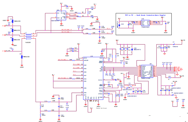
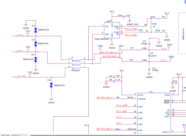
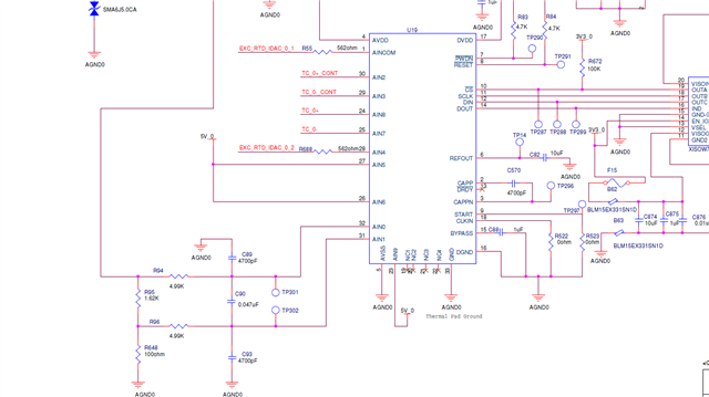
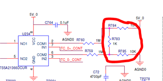
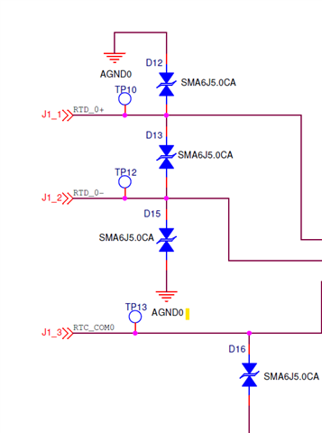
below is the our customer circuit

We have single terminal, So we need to connect both RTD and TC in same terminal, but at a time one should be there in the board

  • Hi Balaji Balaji,

    Can you please explain what the issue is with the thermocouple (TC) measurements? I understand there is some error, but can you please describe in detail what you are seeing and what you expect? How are you determining that there are 5-6 degrees of difference? Is the reading stable, but it is offset by this many degrees? Or is the data moving around a lot? Again, please be detailed, and provide measurement data where possible

    Also, can you provide a larger image of the schematic? That one is very hard to read because it shows up very small on my screen (even after it opens up in a new window).

    -Bryan

  • Dear bryan,

    First of all thanks for your quick reply

    Can you please explain what the issue is with the thermocoupler (TC) measurements?

    We have used 16- ADS1261 IC for our customer product, Each ADS1261 has to be read one TC or one RTD, Please refer the schematic image

    the issue is we have read all 16 channels with Thermocoupler and software side we convert degree and see that in our HMI live data viewer, In that we got 5 to 6 degree difference in each channels, but in connector we have connected RTD its give correct value in RTD, 

    In TC only we have difference , and they have used one analog switch on this , please refer the schematic and excel datas


    Results Excepted
    Cold junction compensation
    TC K type RTD (Pt100)
    TE50_13_1 TE50_13_2 TE50_13_3 TE50_13_4 TE50_13_5 TE50_13_6 TE50_13_7 TE50_13_8 TE50_13_12 (heat source) CJ01 CJ02
    4.466 4.589 4.229 4.972 5.69 5.441 6.431 6.92 2.599 23.432 22.44
    4.465 4.589 4.229 4.972 5.69 5.44 6.431 6.92 2.599 23.432 22.549
    4.465 4.589 4.229 4.972 5.69 5.44 6.431 6.92 2.6 23.432 22.549
    4.465 4.589 4.229 4.972 5.69 5.44 6.325 6.807 2.6 23.328 22.549
    4.464 4.59 4.229 4.972 5.69 5.44 6.325 6.807 2.6 23.328 22.549
    4.464 4.59 4.339 5.011 5.691 5.44 6.45 6.932 2.6 23.449 22.549
    4.464 4.59 4.339 4.999 5.691 5.44 6.45 6.932 2.6 23.449 22.432
    4.463 4.59 4.339 4.999 5.691 5.44 6.45 6.932 2.6 23.449 22.432
    4.463 4.59 4.339 5.106 5.691 5.439 6.45 6.932 2.6 23.449 22.432
    4.463 4.591 4.339 5.106 5.691 5.439 6.45 6.932 2.6 23.449 22.432
    4.462 4.591 4.339 5.084 5.691 5.439 6.45 6.932 2.6 23.449 22.432
    4.462 4.591 4.339 5.015 5.692 5.439 6.45 6.932 2.6 23.449 22.432
    4.462 4.591 4.339 5.081 5.692 5.439 6.45 6.932 2.6 23.449 22.432
    4.461 4.592 4.339 5.032 5.692 5.439 6.45 6.932 2.6 23.449 22.432
    4.461 4.592 4.339 5.076 5.692 5.439 6.45 6.932 2.6 23.449 22.432
    4.461 4.592 4.339 5.094 5.692 5.438 6.45 6.932 2.601 23.449 22.432
    4.461 4.592 4.339 5.006 5.692 5.438 6.45 6.932 2.601 23.449 22.432
    4.46 4.592 4.339 5.006 5.693 5.438 6.45 6.932 2.601 23.449 22.432
    4.46 4.593 4.329 5.006 5.693 5.438 6.434 6.918 2.601 23.44 22.432
    4.46 4.593 4.344 5.035 5.693 5.438 6.451 6.833 2.601 23.455 22.432
    4.459 4.593 4.344 5.011 5.693 5.438 6.451 6.833 2.601 23.455 22.432
    4.459 4.593 4.344 4.98 5.693 5.438 6.451 6.833 2.601 23.455 22.535
    4.459 4.594 4.344 4.98 5.693 5.437 6.451 6.833 2.601 23.455 22.535
    4.458 4.485 4.232 4.98 5.693 5.437 6.342 6.833 2.601 23.347 22.535
    4.458 4.485 4.232 4.98 5.694 5.437 6.342 6.833 2.601 23.347 22.535
    4.458 4.596 4.232 4.987 5.694 5.437 6.342 6.833 2.601 23.347 22.535
    4.457 4.596 4.232 4.987 5.694 5.437 6.342 6.833 2.601 23.347 22.535
    4.457 4.596 4.232 4.989 5.694 5.437 6.342 6.833 2.602 23.347 22.535
    4.457 4.596 4.232 4.989 5.694 5.437 6.342 6.833 2.602 23.347 22.535
    4.456 4.596 4.244 4.974 5.694 5.436 6.342 6.833 2.602 23.357 22.535
    4.456 4.596 4.339 5.043 5.695 5.436 6.342 6.833 2.602 23.446 22.428
    4.456 4.596 4.339 4.986 5.695 5.436 6.342 6.833 2.602 23.446 22.428
    4.456 4.596 4.339 4.986 5.695 5.436 6.342 6.833 2.602 23.446 22.428
    4.455 4.596 4.339 4.986 5.695 5.436 6.342 6.833 2.602 23.446 22.428
    4.455 4.596 4.339 5.092 5.695 5.436 6.342 6.833 2.602 23.446 22.428
    4.455 4.596 4.339 4.995 5.695 5.436 6.342 6.833 2.602 23.446 22.428
    4.454 4.596 4.339 5.049 5.696 5.435 6.342 6.833 2.602 23.446 22.428
    4.454 4.596 4.339 5.07 5.696 5.435 6.342 6.833 2.602 23.446 22.428
    4.454 4.596 4.339 4.997 5.696 5.435 6.442 6.833 2.602 23.446 22.53
    4.453 4.596 4.339 4.997 5.696 5.435 6.442 6.833 2.603 23.446 22.53
    4.453 4.596 4.339 4.993 5.696 5.435 6.442 6.833 2.603 23.446 22.425
    4.453 4.596 4.339 4.993 5.696 5.435 6.442 6.833 2.603 23.446 22.425
    4.452 4.596 4.339 4.993 5.697 5.435 6.442 6.833 2.603 23.446 22.425
    4.452 4.596 4.339 4.989 5.697 5.434 6.34 6.833 2.603 23.446 22.425
    4.452 4.596 4.339 4.989 5.697 5.434 6.34 6.833 2.603 23.446 22.425
    4.451 4.596 4.339 5.042 5.697 5.434 6.34 6.833 2.603 23.446 22.425
    4.451 4.596 4.339 5.065 5.697 5.434 6.34 6.833 2.603 23.446 22.425
    4.451 4.596 4.339 4.997 5.697 5.434 6.34 6.833 2.603 23.446 22.425
    4.45 4.49 4.228 4.984 5.698 5.434 6.34 6.833 2.603 23.336 22.425
    4.45 4.49 4.228 4.984 5.698 5.434 6.34 6.833 2.603 23.336 22.426
    4.45 4.49 4.228 4.984 5.698 5.433 6.34 6.833 2.603 23.336 22.426
    4.45 4.49 4.228 4.984 5.698 5.433 6.34 6.833 2.604 23.336 22.538
    4.449 4.49 4.228 4.984 5.698 5.433 6.34 6.833 2.604 23.336 22.538
    4.449 4.49 4.228 4.984 5.698 5.433 6.34 6.833 2.604 23.336 22.538
    4.449 4.49 4.228 4.984 5.698 5.433 6.34 6.833 2.604 23.336 22.538
    4.448 4.598 4.336 5.005 5.699 5.433 6.34 6.833 2.604 23.436 22.538
    4.448 4.598 4.335 5.1 5.699 5.433 6.34 6.833 2.604 23.435 22.438
    4.448 4.598 4.335 5.1 5.699 5.432 6.34 6.833 2.604 23.435 22.438
    4.447 4.598 4.335 5.1 5.699 5.432 6.34 6.833 2.604 23.435 22.438
    4.447 4.598 4.335 5.1 5.699 5.432 6.34 6.833 2.604 23.435 22.438
    4.447 4.598 4.334 5.1 5.699 5.432 6.34 6.833 2.604 23.435 22.438
    4.446 4.598 4.334 5.1 5.7 5.432 6.34 6.833 2.604 23.434 22.438
    4.446 4.598 4.334 4.992 5.7 5.432 6.34 6.833 2.604 23.434 22.438
    4.446 4.597 4.333 5.083 5.7 5.432 6.34 6.833 2.604 23.434 22.438
    4.445 4.597 4.333 5.066 5.7 5.431 6.34 6.833 2.605 23.434 22.438
    4.445 4.597 4.333 5.008 5.7 5.431 6.452 6.933 2.605 23.433 22.438
    4.557 4.597 4.333 5.084 5.7 5.431 6.452 6.933 2.605 23.433 22.438
    4.526 4.597 4.332 5.104 5.701 5.431 6.35 6.919 2.605 23.433 22.438
    4.539 4.597 4.332 5.011 5.701 5.431 6.35 6.932 2.605 23.433 22.438

    can you please describe in detail what you are seeing and what you expect?

    Actually, our application is reading a thermocoupler [ E, J, K, N, R, S, T, B types of standard thermocouples ] and RTD [3-wire Pt10, Pt100, Cu50, Cu100, BA1, Cu10, Cu53 types of standard RTD inputs] sensors.

    Why i am telling all these information because we have connected in single connector to connect both TC and RTD, which one is required we just connect anyone.

    We suspect circuit is correct or not , and the filter designed also is correct or not, Please check and give us solution for this Is that circuit change or need to check in software side anything...

    If you need more clarity image, please share your email i will send this schematic or i will share my mail id please send ping me i will reply to you r-balaj@hcl.com

  • Hi Balaji Balaji,

    Can you send me the schematic via private message on e2e? You can hover over my name (Bryan Lizon86) and then hit request friendship. At that point you should be able to share the schematic with me only i.e. it will not be visible to anyone else

    -Bryan

  • Hi bryan,

    I could not able to insert, So i split our the image, Kindly connect all the 3 image and let me know if any further clarity image

    and please review that and give us your valuable response

    1...

    2..

    3..

    Thanks & Regards,

    Balaji. R

  • Hi Balaji Balaji,

    Thanks for sharing this information, this is easier to read now

    What is the purpose of these resistors: I understand that R760 and R759 are pull-up / pull-down resistors to bias the TC, but I am not sure what these other resistors are doing. Can you explain?

    Also, how do you measure the thermocouple cold junction? I don't see that measurement on this schematic

    -Bryan

  • Hi bryan,

    Thanks for your reply

    What is the purpose of these resistors: I understand that R760 and R759 are pull-up / pull-down resistors to bias the TC, but I am not sure what these other resistors are doing. Can you explain?

    --> Even we dont know about these resistors, thus what i shared to you, because our customer already made that, so now we are seeing the problems in TC as i said earlier and i saw your recommendation and datasheet for all those it mentioned bias resistor only 1Mohm, 

    When Thermocouple is connecting the analog switch[TS5A21366DCUR] will CLOSE and add these resistors, If RTD is connected the analog switch is OPEN , Thus what we observe. 

    We testing TP280 and TP282, We got around 2.5V voltage, Actually if we read Thermocouple directly there is mV is coming. when this resistor added the voltage is higher and add the input of IC.

    Why switch is used means we have two sensor variant both are connected in one single terminal that is J1_1,J1_2 and J1_3, but at a time only one is connected. So on this time if TC is connected switch is used and it is close state, If RTD is connected switch is open state

    Also, how do you measure the thermocouple cold junction? I don't see that measurement on this schematic

    --> Using thermistor [ LMT70YFQR] is connected directly to uC.

  • Hi Balaji Balaji,

    Can you try removing these resistors (R783, R784, and R785) and see if this makes a difference? You could probably leave R784 and R785 installed, as this just adds to the 1M resistance, but R783 should be removed. Let me know if this improves the results

    -Bryan

  • Hi bryan,

    We removed R783 and tested but difference is not there and increase 2 or 3 degree more...compare than previous

  • Hi Balaji Balaji,

    In a previous post you said the following:

    We testing TP280 and TP282, We got around 2.5V voltage

    However, in the image you highlighted test points TP280 and TP281. I also could not find TP282 on your schematic, but maybe I missed it somewhere. Can you please explain what measurements you are taking to get 2.5V?

    Do you have a high precision meter (e.g. Keysight/HP 3458) where you can take measurements across the ADC inputs during the TC measurements (TP278 and TP279)? We should see if they match the raw ADC output code.

    You could also try enabling the ADC's VBIAS feature instead of using the switch + pullup + pull-down resistors. This feature is connected to AINCOM, which is connected to your net "EXC_RTD_IDAC_0_1". This should bias the thermocouple to a mid-supply voltage. Let's see if this improves the results at all so we can narrow down if the switch + resistors is causing an issue

    -Bryan