This thread has been locked.

If you have a related question, please click the "Ask a related question" button in the top right corner. The newly created question will be automatically linked to this question.

ADS1261: ADS1261 AC temperature sensor readout

Part Number: ADS1261

Dear Bryan,

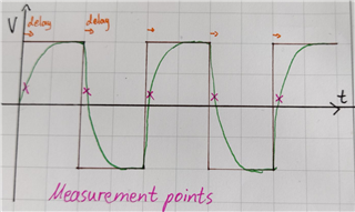
I have built a Wheatstone bridge temperature sensor and using the AC-readout.

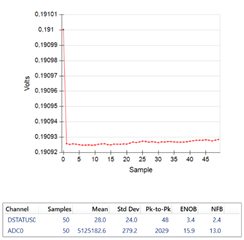
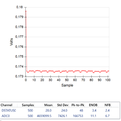
From the data sheet i should have a noise performance down to 0.016µV_RMS (32Gain)

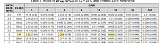
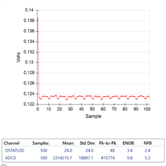
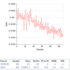
I did a measurement myself and got pretty much the same results.

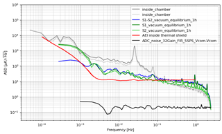
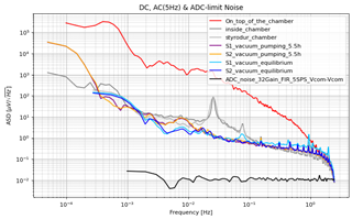
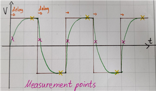
The measurement of my temperature sensors (which are in vacuum and thermally isolated) are showing a "shoulder" at high frequencies.

I was expecting a flat noise at high frequencies.

Do you have any idea where this is coming from?

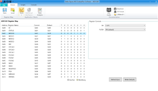
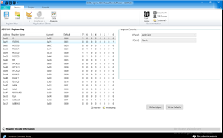
Below are my settings:

Best regards,

Marcel Beck

  • Hi Marcel Beck,

    Can you please explain what you have done thus far to attempt to locate the source of this high frequency noise?

    Also, can you please provide data so we know what is meant by "shoulder at high frequencies"?

    -Bryan

  • Hi Bryan,

    i think my plot was not uploaded ...

    second try:

    Hopefully you can see it this time.

    Best regards,

    Marcel

    btw: we are using the usb from the computer as a voltage source (was also done when taking the noise limit measurement)

  • The red plot is another measurement and not mine

  • Hi Marcel Beck,

    The plots you sent shows spectral density for f <1 Hz (low frequency noise). However, you said you saw high frequency noise. Can you confirm?

    You also mentioned a shoulder - what are you talking about specifically?

    -Bryan

  • "high frequencies" are in my case > 1mHz

    The "shoulder" is the steep immediate rise of the noise starting from my sampling rate (5SPS). 

    I was expecting a flat noise until "real" temperature noise has an impact.

    -Marcel

  • Hi Marcel Beck,

    This appears to be 1/f noise, which becomes more prevalent the longer you sample. And you appear to be sampling for a long time

    Does your sensor have low frequency noise?

    -Bryan

  • I am more worried about the higher frequencies (> 1mHz ).

    Why is there the sudden increase in noise starting from the SPS/2 rate ? Is it really sensor noise?

    I would have thought that the noise is white for high frequencies (>1Hz) and increases by sensor (temp) noise for lower frequencies (like it is doing).

    What is also kinda weird to me is the measurement result when increasing the sampling rate (see pictures below)

    5sps

    100sps

    400sps

    400sps and 17.8ms delay (before it was always 50µs default)

    Best regards,

    Marcel

  • Hi Marcel Beck,

    I think it would be more useful to look at your data in the time domain, as opposed to over frequency. Especially since you are measuring temperature, which is effectively a DC signal. These last few plots make more sense to me as far as what you are trying to measure and how you should be reviewing the data

    Interestingly, the plot showing 5 SPS and the plot showing 400 SPS (+ extra delay) are measuring the same voltage magnitude, as long as you exclude that first odd data point from the 5 SPS plot. Are you seeing some sort of settling issue then?

    That plot also shows what appears to be a drift error. That could be long-term drift, or temperature drift on the EVM itself. Is the EVM in a thermally-controlled space?

    The other plots (100SPS and 400SPS, no delay) show what appears to be some sort of periodic signal in the waveform, possibly some low frequency switching? Have you performed an FFT on this data to identify the frequency(s) of this signal?

    -Bryan

  • The FFT of the 100 and 400sps (default delay) would result in different frequency peaks since the periodic signal seems to be proportional to the sampling rate and not the time.

    Looking at the ASD in [µV/sqrt(Hz)], (see figure below blue and grey plots) could one of the plots from 7.8 (ADS126x Precision, 5-channel and 10-channel, 40-kSPS, 24-bit, delta-sigma ADCs with PGA and monitors) be already causing a readout limit?

    Best regards,

    Marcel

  • Hi Marcel Beck,

    I did not receive answers to several of my questions, and I don't understand your last question. Is there a specific plot you are referencing in section 7.8?

    Also, if you take data for several hours, you are going to see drift errors as I mentioned in my previous post. These will look like 1/f noise in the spectral density plot, so your results make sense.

    -Bryan

  • Hi Bryan,

    i think i found the problem which might be aliasing since i am sampling with 5Hz and the cutoff-freq of the antialisaing-filter on the board is 75kHz. 

    There for, all of the noise (2.5Hz < Noise < 75kHz) reflects symmetrically back into the lower frequency range (Shannon/Nyquist).

    The measuring bridge has a very high impedance. The resistors produce a lot of noise and your current across the bridge is very small. In this case, the bridge becomes an antenna and captures true loose signals that accumulate again in the 1st Nyquist zone.

    Is there any antialiasing filter which i can set or do i need to coonnect an analog infront of the EvalBoard?

    Best regards,

    Marcel

  • Hi Marcel Beck,

    You can change the values of the anti-aliasing filter by replacing the components on the board. However, the caps should be ceramic (C0G) for their low voltage coefficient and improved performance. This will limit the capacitance value you can use. Additionally, increasing the resistance will add noise to your system, so the resistance cannot be made arbitrarily large.

    Alternatively, you could try use an active filter, though this would likely add noise and error to your measurements. It would also need to be added externally, there is no option for adding such a filter directly to the EVM

    -Bryan

  • Hi Bryan,

    i set up an antialiasing filter as a simple RC circuit (F_cutoff=50Hz). My sampling rate is 5 (=5Hz)

    When measuring with DC i get what i expect. (0.2V in my case)

    But when using the AC readout i get a measurement close to 0V.

    My guess is that the measurement after changing the polarity is done immediately (50µs=delay default), there for the capacitor is not fully charged yet.

    The maximum i can select for the delay is 17.8ms which would still be to close/fast after the polarity change. 

    The drawing below should explain my concerns:

    What i want is that the measurement is taken at the yellow points (see picture below):

    Is there any way to make this happen without writing my own code?

    BTW: increasing the cutoff frequency of my filter would counter act the purpose so that's not an option.

    Best regards,

    Marcel

  • Hi Marcel Beck,

    Regarding this comment:

    My guess is that the measurement after changing the polarity is done immediately (50µs=delay default), there for the capacitor is not fully charged yet.

    Yes, this is the challenge with decreasing the anti-aliasing filter bandwidth, which increases the analog settling time of the circuit. If you want to use the AC excitation feature then you will have to change the AA filter cutoff frequency.

    -Bryan

  • Increasing the AA filter cutoff frequency would result in not filtering the noise from my sampling rate to the 75kHz AA filter of the board.

    Is that a problem i am stuck with till i write my own code or is there a work around?

    - Marcel

  • Hi Marcel Beck,

    I am not sure how you can resolve this issue with code, other than manually controlling the entire AC excitation process. The ADC automatically adds the delay and performs the switching, there is no point at which you can just insert another delay into this process. instead you would have to manually control the switches, then add a delay to wait for the filter to settle, then take a measurement, then swap the excitation voltage, then add a delay to wait for the filter to settle, then take another measurement, and then perform the math in your code to determine the final ADC code value from the two measurements. You will also need to manually control the reference swapping because again, this is done automatically by the ADC. This will require another set of switches

    I would recommend not using the AC excitation feature because it appears to causing more problems than it is solving at this point.

    -Bryan