This thread has been locked.

If you have a related question, please click the "Ask a related question" button in the top right corner. The newly created question will be automatically linked to this question.

ADS7828: Interpreting readout and understanding address numbers used

Part Number: ADS7828

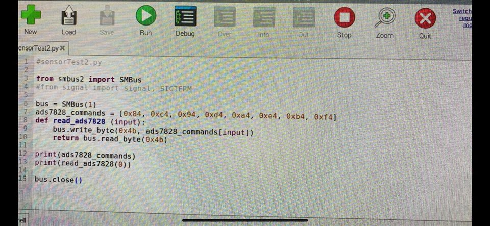
We are using the smbus2 library in Python to read data coming originally from a TMSC1108-Q1 current sensor (analog) which is sent through an ADS7828 ADC and communicated to a Raspberry Pi via I2C protocol. We defined an array of length 8 with the value at each index representing a different channel: ads7828_commands = [0x84, 0xc4, 0x94, 0xd4, 0xa4, 0xe4, 0xb4, 0xf4]. We then create a function that takes one argument, an integer between 0 and 7 inclusive named "input”, and within the function we have "bus.write_byte(0x4b, ads7828_commands[input])" followed by "return bus.read_byte(0x4b)." Note that 0x4b is the address of this ADC.


We have two main areas that we would like to resolve and gain better clarity on:
1. When we test the function with different "input" values, for a value of 0 we tend to see an output of 15, for a value of 1 we tend to get 15, and usually for a value of 2 or more the output slowly drops to 0 over time (if we click the run button fast enough the terminal prints out descending integer values.) Is there a significance to the number 15? And why is that the value for those specific addresses? 
2. If we input "0x04" or “0x14” (for example) instead of “0x84" we also get 15 as an output value. However, if we try a higher number like "0x54" we get 0. What is the cause of these results?
 
We are having trouble both interpreting the output of the function and also understanding the purpose of the addresses in ads7828_commands. Please let us know if you have any insight into why our code/circuit is behaving this way.
 
I have attached below a picture of the simple test code for the sensor/ADC.
 
Thank you!
 
  • Hi Christopher,

    When you refer to addresses above, are you actually referring to the channel selection bits in the command byte?  If so, you would decode that in Table II.  Writing [0x84, 0xc4, 0x94, 0xd4, 0xa4, 0xe4, 0xb4, 0xf4] to the command byte is setting the SD bit and the PD0 bit and selecting CH 0-7.  The inputs in that case are all single ended and referenced to the COM input pin, which is normally held at ground.  If you input "0x04" or “0x14”, you still have the PD0 bit set, but now you are changing the reference point of the input channel.  The 04 selects CH1 at the positive input and CH2 as the negative input.  Not sure why you get '15' but I suspect you are not applying the proper voltage levels at the input pins.  A schematic would be helpful.

  • Hi Tom,

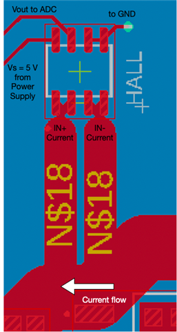
    Thanks for the clarifying about the addresses! Regarding the other question, I have attached an image of the PCB design in the region of the Hall sensor (datasheet can be found here: https://www.ti.com/lit/ds/symlink/tmcs1107.pdf?HQS=dis-dk-null-digikeymode-dsf-pf-null-wwe&ts=1687474618781, we're using the TMCS1107A4B). We tested the Vout before it reaches the ADC and found that the voltage does not seem to change value from the 0 A offset voltage of 2.5 V, even when we have 1 A of current running. One potential issue I see could be if not much current is not reaching the IN- and IN+ channels since the traces are smaller width and form an overall higher resistance path than the shortest path. Let me know if you see any issues here, and if we should be doing something differently. Also, does the 2.5V Vout help clarify why we're getting a readout of 15 from the ADC?


  • Hi Christopher,

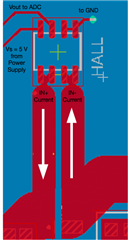
    The first thing you need to cut the trace that shorts IN+ to IN-, the current you are trying to sense must flow through the TMCS device.  Something like this should work:

    The ADS7828 has an input range of 0-Vref.  If you are using the internal 2.5V reference, then the '0 current' value of 2.5V is already at the full scale voltage of the ADC input.  You could sense negative current to -25A.  If the Vref of the ADS7828 is connected to 5V, you should be able to sense the full -25A to +25A range of the TMCS.  Not sure what the '15' is - with a 2.5V reference, 2.5V at the input should be 0xFFF output code.  A 5V reference should give you 0x7FF.