Other Parts Discussed in Thread: ADS131M08,
Hi,
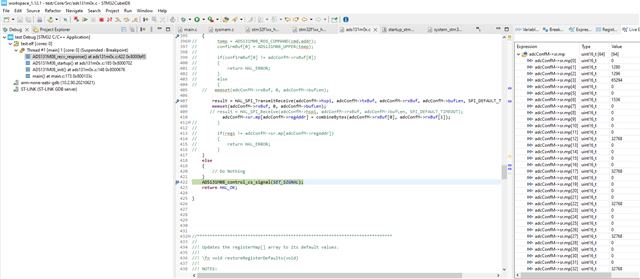
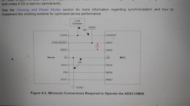
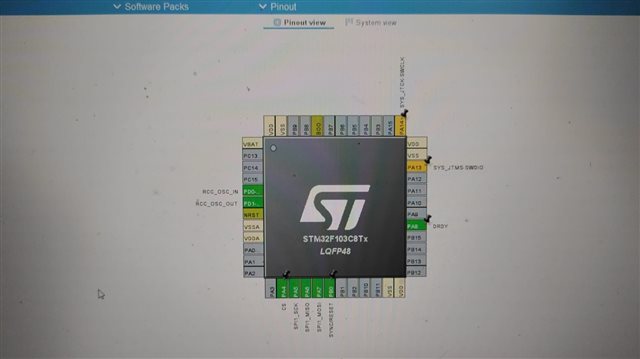
I am trying to interface Stm32f103 controller with ADS131m08 Evaluation board and i am facing issue in reading the register back such as when ever i try to write some register let say Clock register i try to read it back so it replace the value in the register refer for the same is given in the snippet share below .
Kindly help me in reading back the register and i have already try the method given in the reference code for ADS131m08 but it didnot work.
I am attaching my ads131m0x.c file in this there are 2 function one is for send command and other is recv_response so I am not able to read response of the register that i write but my recv_response work well with the commands.
Please help me in reading back the register correctly.
/**
 * \copyright Copyright (C) 2019 Texas Instruments Incorporated - http://www.ti.com/
 *
 *  Redistribution and use in source and binary forms, with or without
 *  modification, are permitted provided that the following conditions
 *  are met:
 *
 *    Redistributions of source code must retain the above copyright
 *    notice, this list of conditions and the following disclaimer.
 *
 *    Redistributions in binary form must reproduce the above copyright
 *    notice, this list of conditions and the following disclaimer in the
 *    documentation and/or other materials provided with the
 *    distribution.
 *
 *    Neither the name of Texas Instruments Incorporated nor the names of
 *    its contributors may be used to endorse or promote products derived
 *    from this software without specific prior written permission.
 *
 *  THIS SOFTWARE IS PROVIDED BY THE COPYRIGHT HOLDERS AND CONTRIBUTORS
 *  "AS IS" AND ANY EXPRESS OR IMPLIED WARRANTIES, INCLUDING, BUT NOT
 *  LIMITED TO, THE IMPLIED WARRANTIES OF MERCHANTABILITY AND FITNESS FOR
 *  A PARTICULAR PURPOSE ARE DISCLAIMED. IN NO EVENT SHALL THE COPYRIGHT
 *  OWNER OR CONTRIBUTORS BE LIABLE FOR ANY DIRECT, INDIRECT, INCIDENTAL,
 *  SPECIAL, EXEMPLARY, OR CONSEQUENTIAL DAMAGES (INCLUDING, BUT NOT
 *  LIMITED TO, PROCUREMENT OF SUBSTITUTE GOODS OR SERVICES; LOSS OF USE,
 *  DATA, OR PROFITS; OR BUSINESS INTERRUPTION) HOWEVER CAUSED AND ON ANY
 *  THEORY OF LIABILITY, WHETHER IN CONTRACT, STRICT LIABILITY, OR TORT
 *  (INCLUDING NEGLIGENCE OR OTHERWISE) ARISING IN ANY WAY OUT OF THE USE
 *  OF THIS SOFTWARE, EVEN IF ADVISED OF THE POSSIBILITY OF SUCH DAMAGE.
 *
 */

#include "ads131m0x.h"
#include "stm32f1xx_hal.h"
#include "stm32f1xx_it.h"
#include "string.h"
#include "gpio.h"
#include <stdlib.h>
//****************************************************************************
//
// Internal variables
//
//****************************************************************************
_adcConfM* adcConfM = NULL;
_ADS131M08_ch ch;
#define SPI_DEFAULT_TIMEOUT 100U

//****************************************************************************
//
// Internal function prototypes
//
//****************************************************************************
//
//uint8_t     buildSPIarray(const uint16_t opcodeArray[], uint8_t numberOpcodes, uint8_t byteArray[]);
//uint16_t    enforce_selected_device_modes(uint16_t data);
//uint8_t     getWordByteLength(void);
uint16_t getRegisterValue(uint8_t address);
HAL_StatusTypeDef ADS131M08_send_command(uint16_t cmd, uint16_t addr, uint16_t regs);
HAL_StatusTypeDef ADS131M08_recv_response(uint16_t cmd, uint16_t addr, uint16_t regs, _sendFlg sendFlg);
extern void ADS131M08_control_cs_signal(_signalState onOff);
extern GPIO_PinState ADS131M08_read_cs_signal();
void restoreRegisterDefaults(void);
extern uint8_t ADS131M08_wait_drdy_int(const uint32_t timeout_10ms);
HAL_StatusTypeDef ADS131M08_startup();
float ADS131M08_convert_to_mVolt(uint32_t reg);
void delay_us(uint32_t microseconds);
void toggleRESET(void);
uint8_t confirmBuf[2];
//*****************************************************************************
//
//! Getter function to access registerMap array from outside of this module.
//!
//! \fn uint16_t getRegisterValue(uint8_t address)
//!
//! NOTE: The internal registerMap arrays stores the last know register value,
//! since the last read or write operation to that register. This function
//! does not communicate with the device to retrieve the current register value.
//! For the most up-to-date register data or retrieving the value of a hardware
//! controlled register, it is recommend to use readSingleRegister() to read the
//! current register value.
//!
//! \return unsigned 16-bit register value.
//
//*****************************************************************************
uint16_t getRegisterValue(uint8_t address)
{
    assert(address < NUM_REGISTERS);
    return adcConfM->sr.mp[address];
}

//*****************************************************************************
//
//! Example start up sequence for the ADS131M0x.
//!
//! \fn void adcStartup(void)
//!
//! Before calling this function, the device must be powered,
//! the SPI/GPIO pins of the MCU must have already been configured,
//! and (if applicable) the external clock source should be provided to CLKIN.
//!
//! \return None.
//
//*****************************************************************************


HAL_StatusTypeDef ADS131M08_init(_adcType adcType, SPI_HandleTypeDef* hspi)
{
    HAL_StatusTypeDef result = HAL_OK;
    _adcConfM* adcConf;

    if(adcType == ADS131M08_ADC1)
    {
        adcConfM  = (_adcConfM*)malloc(sizeof(_adcConfM));
        memset(adcConfM, 0, sizeof(_adcConfM));
        adcConfM->type            = adcType;
        adcConfM->stat            = ADS131M08_INIT;
        adcConfM->hspi            = hspi;
        adcConfM->nReset.port     = SYNC_RESET_GPIO_Port;
        adcConfM->nReset.pin      = SYNC_RESET_Pin;
        adcConfM->cs.port         = CS_GPIO_Port;
        adcConfM->cs.pin          = CS_Pin;
        adcConfM->nDrdy.port      = DRDY_GPIO_Port;
        adcConfM->nDrdy.pin       = DRDY_Pin;
        adcConfM->bufLen          = M08_WORDS_IN_FRAME * M08_WORD_LENGTH;      // 9 Words x 24 Bits
        adcConfM->rxBuf           = (uint8_t*)malloc(adcConfM->bufLen);
        memset(adcConfM->rxBuf, 0, adcConfM->bufLen);
        adcConfM->txBuf           = (uint8_t*)malloc(adcConfM->bufLen);
        memset(adcConfM->txBuf, 0, adcConfM->bufLen);

        adcConf = adcConfM;
    }
    else
    {
        result = HAL_ERROR;
        return result;
    }

    // Reset Sequence
    HAL_GPIO_WritePin(adcConf->cs.port, adcConf->cs.pin, GPIO_PIN_SET);
    HAL_GPIO_WritePin(adcConf->nReset.port, adcConf->nReset.pin, GPIO_PIN_RESET);

    result = ADS131M08_startup();

    if(result == HAL_OK)
    {
        adcConf->stat = ADS131M08_NORMAL;
    }
    else
    {
        adcConf->stat = ADS131M08_INIT_FAIL;
    }

    return result;
}


HAL_StatusTypeDef ADS131M08_startup()

{
	int i=0;
	uint16_t regs=0;
	/* (OPTIONAL) Provide additional delay time for power supply settling */
	HAL_Delay(50);

	/* (REQUIRED) Set nRESET pin high for ADC operation */
    HAL_GPIO_WritePin(adcConfM->nReset.port, adcConfM->nReset.pin, GPIO_PIN_SET);

	/* (OPTIONAL) Toggle nRESET pin to ensure default register settings. */
	/* NOTE: This also ensures that the device registers are unlocked.	 */
	toggleRESET();

    /* (REQUIRED) Initialize internal 'registerMap' array with device default settings */
	restoreRegisterDefaults();

    /* (OPTIONAL) Validate first response word when beginning SPI communication: (0xFF20 | CHANCNT) */
	 ADS131M08_send_command(ADS131M08_CMD_NULL, 0, 0);
	 ADS131M08_send_command(ADS131M08_CMD_UNLOCK, 0, 0);

	    if(HAL_OK != ADS131M08_recv_response(ADS131M08_CMD_UNLOCK, 0, 0, SEND_SYSTEM_CMD))
	    {
	        return HAL_ERROR;
	    }

	    ADS131M08_send_command(ADS131M08_CMD_WAKEUP, 0, 0);

	    if(HAL_OK != ADS131M08_recv_response(ADS131M08_CMD_WAKEUP, 0, 0, SEND_SYSTEM_CMD))
	    {
	        return HAL_ERROR;
	    }
	/* (OPTIONAL) Define your initial register settings here */
	    regs=(CLOCK_DEFAULT & ~CLOCK_OSR_MASK);
	    regs|=CLOCK_OSR_256;
       ADS131M08_send_command(ADS131M08_CMD_WREG,CLOCK_ADDRESS, regs);
	    if(HAL_OK != ADS131M08_recv_response(ADS131M08_CMD_RREG, CLOCK_ADDRESS, 0, SEND_REGISTER_CMD))
	    {
	        return HAL_ERROR;
	    }
    /* (REQUIRED) Configure MODE register settings
     * NOTE: This function call is required here for this particular code implementation to work.
     * This function will enforce the MODE register settings as selected in the 'ads131m0x.h' header file.
     */
       ADS131M08_send_command(ADS131M08_CMD_WREG,MODE_ADDRESS, MODE_DEFAULT);

    /* (OPTIONAL) Read back all registers */
    // Wakeup device


    // Ignore the first 5 conversion results to allow for the
    // output buffers to fill-up and the SINC3 filter to settle
    for(i = 0; i < 5; i++)
    {
        ADS131M08_wait_drdy_int(100);
        ADS131M08_control_cs_signal(RESET_SIGNAL);
        HAL_SPI_Receive(adcConfM->hspi, adcConfM->rxBuf, adcConfM->bufLen, SPI_DEFAULT_TIMEOUT);
        ADS131M08_control_cs_signal(SET_SIGNAL);
    }

    return HAL_OK;
	/* (OPTIONAL) Check STATUS register for faults */
}

//*****************************************************************************
//
//! Toggles the "nSYNC/nRESET" pin to trigger a reset
//! (LOW, delay 2 ms, then HIGH).
//!
//! \fn void toggleRESET(void)
//!
//! \return None.
//
//*****************************************************************************
void toggleRESET(void)
{
    /* --- INSERT YOUR CODE HERE --- */
    HAL_GPIO_WritePin(adcConfM->nReset.port, adcConfM->nReset.pin, GPIO_PIN_RESET);

    // Minimum /RESET pulse width (tSRLRST) equals 2,048 CLKIN periods (1 ms @ 2.048 MHz)
    HAL_Delay(2);

    HAL_GPIO_WritePin(adcConfM->nReset.port, adcConfM->nReset.pin, GPIO_PIN_SET);
    // tREGACQ delay before communicating with the device again
    delay_us(5);

    // NOTE: The ADS131M0x's next response word should be (0xFF20 | CHANCNT).
    // A different response may be an indication that the device did not reset.

    // Update register array
  //  restoreRegisterDefaults();

    // Write to MODE register to enforce mode settings

}


//*****************************************************************************
//
//! Sends the specified SPI command to the ADC (NULL, STANDBY, or WAKEUP).
//!
//! \fn uint16_t sendCommand(uint16_t opcode)
//!
//! \param opcode SPI command byte.
//!
//! NOTE: Other commands have their own dedicated functions to support
//! additional functionality.
//!
//! \return ADC response byte (typically the STATUS byte).
//
//*****************************************************************************

HAL_StatusTypeDef ADS131M08_send_command(uint16_t cmd, uint16_t addr, uint16_t regs)
{
    HAL_StatusTypeDef result = HAL_OK;
    _sendFlg sendFlg = SEND_SYSTEM_CMD;
    GPIO_PinState pinStat = GPIO_PIN_RESET;

    switch(cmd)
    {
        case ADS131M08_CMD_NULL:
        case ADS131M08_CMD_RESET:
        case ADS131M08_CMD_STANDBY:
        case ADS131M08_CMD_WAKEUP:
        case ADS131M08_CMD_LOCK:
        case ADS131M08_CMD_UNLOCK:
            adcConfM->txBuf[0] = ADS131M08_UPPER(cmd);
            adcConfM->txBuf[1] = ADS131M08_LOWER(cmd);
            adcConfM->txBuf[2] = 0;
            adcConfM->txBuf[3] = 0;
            adcConfM->command = cmd;
            adcConfM->regAddr = 0;

            sendFlg = SEND_SYSTEM_CMD;
            break;

        case ADS131M08_CMD_RREG:    // ADS131A04_CMD_RREGS
            adcConfM->txBuf[0] = ADS131M08_UPPER(ADS131M08_REG_COMMAND(cmd,addr));
            adcConfM->txBuf[1] = ADS131M08_LOWER(ADS131M08_REG_COMMAND(cmd,addr));
            adcConfM->txBuf[2] = 0;
            adcConfM->txBuf[3] = 0;
            adcConfM->command = cmd;
            adcConfM->regAddr = addr;
            adcConfM->regs = regs;

            sendFlg = SEND_REGISTER_CMD;
            break;
        case ADS131M08_CMD_WREG:
            adcConfM->txBuf[0] = ADS131M08_UPPER(ADS131M08_REG_COMMAND(cmd,addr));
            adcConfM->txBuf[1] = ADS131M08_LOWER(ADS131M08_REG_COMMAND(cmd,addr));
            adcConfM->txBuf[2] = ADS131M08_UPPER(regs);
            adcConfM->txBuf[3] = ADS131M08_LOWER(regs);
            adcConfM->command = cmd;
            adcConfM->regAddr = addr;
            adcConfM->regs = regs;
            adcConfM->sr.mp[addr] = regs;

            sendFlg = SEND_REGISTER_CMD;
            break;
        default:
            break;
    }

    // Check availablity to send data

    while(GPIO_PIN_RESET == pinStat)
    {
        pinStat = ADS131M08_read_cs_signal();
    }
    ADS131M08_control_cs_signal(RESET_SIGNAL);

    result = HAL_SPI_TransmitReceive(adcConfM->hspi, adcConfM->txBuf, adcConfM->rxBuf, adcConfM->bufLen, SPI_DEFAULT_TIMEOUT);
    ADS131M08_control_cs_signal(SET_SIGNAL);

    if(sendFlg == SEND_SYSTEM_CMD)
    {
        adcConfM->response = combineBytes(adcConfM->rxBuf[0], adcConfM->rxBuf[1]);
    }
    else if(sendFlg == SEND_REGISTER_CMD)
    {
        adcConfM->sr.mp[adcConfM->regAddr] = regs;
    }

    if(HAL_OK != result)
    {
        ADS131M08_control_cs_signal(SET_SIGNAL);
    }
    else
    {
        // DO NOTHING
    }
    return result;
}


HAL_StatusTypeDef ADS131M08_recv_response(uint16_t cmd, uint16_t addr, uint16_t regs, _sendFlg sendFlg)
{

    uint16_t temp;
    // Initialize buffer to send NULL command
    HAL_StatusTypeDef result = HAL_OK;

    memset(adcConfM->txBuf, 0, adcConfM->bufLen);

    // Check availablity to send data
    while(GPIO_PIN_RESET == ADS131M08_read_cs_signal())
    {}
    ADS131M08_control_cs_signal(RESET_SIGNAL);


    if(sendFlg == SEND_SYSTEM_CMD)
    {
    	   if(HAL_OK != HAL_SPI_TransmitReceive(adcConfM->hspi, adcConfM->txBuf, adcConfM->rxBuf, adcConfM->bufLen, SPI_DEFAULT_TIMEOUT))
    	    {
    	        return HAL_ERROR;
    	    }
        adcConfM->response = combineBytes(adcConfM->rxBuf[0], adcConfM->rxBuf[1]);

        if(cmd != adcConfM->response)
        {
            return HAL_ERROR;
        }
    }
    else if(sendFlg == SEND_REGISTER_CMD)
    {
//        temp = ADS131M08_REG_COMMAND(cmd,addr);
//        confirmBuf[0] = ADS131M08_UPPER(temp);
//
//        if(confirmBuf[0] != adcConfM->rxBuf[0])
//        {
//            return HAL_ERROR;
//        }
//        else
//        {
    //	 memset(adcConfM->rxBuf, 0, adcConfM->bufLen);

        result = HAL_SPI_TransmitReceive(adcConfM->hspi, adcConfM->txBuf, adcConfM->rxBuf, adcConfM->bufLen, SPI_DEFAULT_TIMEOUT);
        memset(adcConfM->rxBuf, 0, adcConfM->bufLen);
       // result = HAL_SPI_Receive(adcConfM->hspi, adcConfM->rxBuf, adcConfM->bufLen, SPI_DEFAULT_TIMEOUT);
            adcConfM->sr.mp[adcConfM->regAddr] = combineBytes(adcConfM->rxBuf[0], adcConfM->rxBuf[1]);
//        }
//
//        if(regs != adcConfM->sr.mp[adcConfM->regAddr])
//        {
//            return HAL_ERROR;
//        }
    }
    else
    {
        // Do Nothing
    }
    ADS131M08_control_cs_signal(SET_SIGNAL);
    return HAL_OK;

}


//*****************************************************************************
//
//! Updates the registerMap[] array to its default values.
//!
//! \fn void restoreRegisterDefaults(void)
//!
//! NOTES:
//! - If the MCU keeps a copy of the ADS131M0x register settings in memory,
//! then it is important to ensure that these values remain in sync with the
//! actual hardware settings. In order to help facilitate this, this function
//! should be called after powering up or resetting the device (either by
//! hardware pin control or SPI software command).
//!
//! - Reading back all of the registers after resetting the device can
//! accomplish the same result; however, this might be problematic if the
//! device was previously in CRC mode or the WLENGTH was modified, since
//! resetting the device exits these modes. If the MCU is not aware of this
//! mode change, then read register commands will return invalid data due to
//! the expectation of data appearing in a different byte position.
//!
//! \return None.
//
//*****************************************************************************
void restoreRegisterDefaults(void)
{
	 adcConfM->sr.mp[ID_ADDRESS]             =   0x00;               /* NOTE: This a read-only register */
	 adcConfM->sr.mp[STATUS_ADDRESS]         =   STATUS_DEFAULT;
	 adcConfM->sr.mp[MODE_ADDRESS]           =   MODE_DEFAULT;
	 adcConfM->sr.mp[CLOCK_ADDRESS]          =   CLOCK_DEFAULT;
	 adcConfM->sr.mp[GAIN1_ADDRESS]          =   GAIN1_DEFAULT;
	 adcConfM->sr.mp[GAIN2_ADDRESS]          =   GAIN2_DEFAULT;
	 adcConfM->sr.mp[CFG_ADDRESS]            =   CFG_DEFAULT;
	 adcConfM->sr.mp[THRSHLD_MSB_ADDRESS]    =   THRSHLD_MSB_DEFAULT;
	 adcConfM->sr.mp[THRSHLD_LSB_ADDRESS]    =   THRSHLD_LSB_DEFAULT;
	 adcConfM->sr.mp[CH0_CFG_ADDRESS]        =   CH0_CFG_DEFAULT;
	 adcConfM->sr.mp[CH0_OCAL_MSB_ADDRESS]   =   CH0_OCAL_MSB_DEFAULT;
	 adcConfM->sr.mp[CH0_OCAL_LSB_ADDRESS]   =   CH0_OCAL_LSB_DEFAULT;
	 adcConfM->sr.mp[CH0_GCAL_MSB_ADDRESS]   =   CH0_GCAL_MSB_DEFAULT;
	 adcConfM->sr.mp[CH0_GCAL_LSB_ADDRESS]   =   CH0_GCAL_LSB_DEFAULT;
#if (CHANNEL_COUNT > 1)
	 adcConfM->sr.mp[CH1_CFG_ADDRESS]        =   CH1_CFG_DEFAULT;
	 adcConfM->sr.mp[CH1_OCAL_MSB_ADDRESS]   =   CH1_OCAL_MSB_DEFAULT;
	 adcConfM->sr.mp[CH1_OCAL_LSB_ADDRESS]   =   CH1_OCAL_LSB_DEFAULT;
	 adcConfM->sr.mp[CH1_GCAL_MSB_ADDRESS]   =   CH1_GCAL_MSB_DEFAULT;
	 adcConfM->sr.mp[CH1_GCAL_LSB_ADDRESS]   =   CH1_GCAL_LSB_DEFAULT;
#endif
#if (CHANNEL_COUNT > 2)
	 adcConfM->sr.mp[CH2_CFG_ADDRESS]        =   CH2_CFG_DEFAULT;
	 adcConfM->sr.mp[CH2_OCAL_MSB_ADDRESS]   =   CH2_OCAL_MSB_DEFAULT;
	 adcConfM->sr.mp[CH2_OCAL_LSB_ADDRESS]   =   CH2_OCAL_LSB_DEFAULT;
	 adcConfM->sr.mp[CH2_GCAL_MSB_ADDRESS]   =   CH2_GCAL_MSB_DEFAULT;
	 adcConfM->sr.mp[CH2_GCAL_LSB_ADDRESS]   =   CH2_GCAL_LSB_DEFAULT;
#endif
#if (CHANNEL_COUNT > 3)
	 adcConfM->sr.mp[CH3_CFG_ADDRESS]        =   CH3_CFG_DEFAULT;
	 adcConfM->sr.mp[CH3_OCAL_MSB_ADDRESS]   =   CH3_OCAL_MSB_DEFAULT;
	 adcConfM->sr.mp[CH3_OCAL_LSB_ADDRESS]   =   CH3_OCAL_LSB_DEFAULT;
	 adcConfM->sr.mp[CH3_GCAL_MSB_ADDRESS]   =   CH3_GCAL_MSB_DEFAULT;
	 adcConfM->sr.mp[CH3_GCAL_LSB_ADDRESS]   =   CH3_GCAL_LSB_DEFAULT;
#endif
#if (CHANNEL_COUNT > 4)
	 adcConfM->sr.mp[CH4_CFG_ADDRESS]        =   CH4_CFG_DEFAULT;
	 adcConfM->sr.mp[CH4_OCAL_MSB_ADDRESS]   =   CH4_OCAL_MSB_DEFAULT;
	 adcConfM->sr.mp[CH4_OCAL_LSB_ADDRESS]   =   CH4_OCAL_LSB_DEFAULT;
	 adcConfM->sr.mp[CH4_GCAL_MSB_ADDRESS]   =   CH4_GCAL_MSB_DEFAULT;
	 adcConfM->sr.mp[CH4_GCAL_LSB_ADDRESS]   =   CH4_GCAL_LSB_DEFAULT;
#endif
#if (CHANNEL_COUNT > 5)
	 adcConfM->sr.mp[CH5_CFG_ADDRESS]        =   CH5_CFG_DEFAULT;
	 adcConfM->sr.mp[CH5_OCAL_MSB_ADDRESS]   =   CH5_OCAL_MSB_DEFAULT;
	 adcConfM->sr.mp[CH5_OCAL_LSB_ADDRESS]   =   CH5_OCAL_LSB_DEFAULT;
	 adcConfM->sr.mp[CH5_GCAL_MSB_ADDRESS]   =   CH5_GCAL_MSB_DEFAULT;
	 adcConfM->sr.mp[CH5_GCAL_LSB_ADDRESS]   =   CH5_GCAL_LSB_DEFAULT;
#endif
#if (CHANNEL_COUNT > 6)
	 adcConfM->sr.mp[CH6_CFG_ADDRESS]        =   CH6_CFG_DEFAULT;
	 adcConfM->sr.mp[CH6_OCAL_MSB_ADDRESS]   =   CH6_OCAL_MSB_DEFAULT;
	 adcConfM->sr.mp[CH6_OCAL_LSB_ADDRESS]   =   CH6_OCAL_LSB_DEFAULT;
	 adcConfM->sr.mp[CH6_GCAL_MSB_ADDRESS]   =   CH6_GCAL_MSB_DEFAULT;
	 adcConfM->sr.mp[CH6_GCAL_LSB_ADDRESS]   =   CH6_GCAL_LSB_DEFAULT;
#endif
#if (CHANNEL_COUNT > 7)
	 adcConfM->sr.mp[CH7_CFG_ADDRESS]        =   CH7_CFG_DEFAULT;
	 adcConfM->sr.mp[CH7_OCAL_MSB_ADDRESS]   =   CH7_OCAL_MSB_DEFAULT;
	 adcConfM->sr.mp[CH7_OCAL_LSB_ADDRESS]   =   CH7_OCAL_LSB_DEFAULT;
	 adcConfM->sr.mp[CH7_GCAL_MSB_ADDRESS]   =   CH7_GCAL_MSB_DEFAULT;
	 adcConfM->sr.mp[CH7_GCAL_LSB_ADDRESS]   =   CH7_GCAL_LSB_DEFAULT;
#endif
	 adcConfM->sr.mp[REGMAP_CRC_ADDRESS]     =   REGMAP_CRC_DEFAULT;
}


//****************************************************************************
//
// Helper functions
//
//****************************************************************************

void ADS131M08_receive_data()
{
    ADS131M08_control_cs_signal(RESET_SIGNAL);
    HAL_SPI_Receive_DMA(adcConfM->hspi, adcConfM->rxBuf, adcConfM->bufLen);
}


//*****************************************************************************
//
//! Takes a 16-bit word and returns the most-significant byte.
//!
//! \fn uint8_t upperByte(uint16_t uint16_Word)
//!
//! \param temp_word is the original 16-bit word.
//!
//! \return 8-bit most-significant byte.
//
//*****************************************************************************
uint8_t upperByte(uint16_t uint16_Word)
{
    uint8_t msByte;
    msByte = (uint8_t) ((uint16_Word >> 8) & 0x00FF);

    return msByte;
}


//*****************************************************************************
//
//! Takes a 16-bit word and returns the least-significant byte.
//!
//! \fn uint8_t lowerByte(uint16_t uint16_Word)
//!
//! \param temp_word is the original 16-bit word.
//!
//! \return 8-bit least-significant byte.
//
//*****************************************************************************
uint8_t lowerByte(uint16_t uint16_Word)
{
    uint8_t lsByte;
    lsByte = (uint8_t) (uint16_Word & 0x00FF);

    return lsByte;
}

uint32_t ADS131M08_convert_adc_data(const uint8_t* dataBuf)
{
    uint32_t upperByte;
    uint32_t middleByte;
    uint32_t lowerByte;

    // The output data extends to 32 bits with eight zeroes(0b00000000, 1Byte) added to the least significant bits when using the 32-bit device word length setting, datasheet 38p
    upperByte    = ((uint32_t) dataBuf[0] << 16);
    middleByte   = ((uint32_t) dataBuf[1] << 8);
    lowerByte  = ((uint32_t) dataBuf[2] << 0);

    return (upperByte | middleByte | lowerByte);
}


void ADS131M08_parse_adc_data()
{

    uint8_t index;

    adcConfM->response = combineBytes(adcConfM->rxBuf[0], adcConfM->rxBuf[1]);

    for(ch = ADC_CH1, index = 1; ch < NUMB_ADC_CH; ch++, index++)
    {
        adcConfM->chData[ch].r = ADS131M08_convert_adc_data(&adcConfM->rxBuf[index * M08_WORD_LENGTH]);
        adcConfM->chData[ch].v = ADS131M08_convert_to_mVolt(adcConfM->chData[ch].r);
    }
}


float ADS131M08_convert_to_mVolt(uint32_t reg)
{
    const float unitFS = 5000.0f / 8388607.0f; // unit: mV (if unit is V, calculated value is out of 'float' range)
	const uint32_t boundaryValue = 0x7FFFFF; // threshold of positive value
	int signFlg = 0;		// +: 1, -: -1

    // negative value
    if (reg > boundaryValue)
    {
        reg = (0xFFFFFF - reg) + 1; // if value is 0xFFFFFF, register is -FS/2^23. so plus 1
        signFlg = -1;
    }
    // positive value
    else
    {
        signFlg = 1;
    }

    // convert register to mVolt
    return (unitFS * (float)reg * (float)signFlg);
}
//*****************************************************************************
//
//! Takes two 8-bit words and returns a concatenated 16-bit word.
//!
//! \fn uint16_t combineBytes(uint8_t upperByte, uint8_t lowerByte)
//!
//! \param upperByte is the 8-bit value that will become the MSB of the 16-bit word.
//! \param lowerByte is the 8-bit value that will become the LSB of the 16-bit word.
//!
//! \return concatenated 16-bit word.
//
//*****************************************************************************
uint16_t combineBytes(uint8_t upperByte, uint8_t lowerByte)
{
    uint16_t combinedValue;
    combinedValue = ((uint16_t) upperByte << 8) | ((uint16_t) lowerByte);

    return combinedValue;
}


//*****************************************************************************
//
//! Combines ADC data bytes into a single signed 32-bit word.
//!
//! \fn int32_t combineDataBytes(const uint8_t dataBytes[])
//!
//! \param dataBytes is a pointer to uint8_t[] where the first element is the MSB.
//!
//! \return Returns the signed-extend 32-bit result.
//
//*****************************************************************************
int32_t signExtend(const uint8_t dataBytes[])
{

#ifdef WORD_LENGTH_24BIT

    int32_t upperByte   = ((int32_t) dataBytes[0] << 24);
    int32_t middleByte  = ((int32_t) dataBytes[1] << 16);
    int32_t lowerByte   = ((int32_t) dataBytes[2] << 8);

    return (((int32_t) (upperByte | middleByte | lowerByte)) >> 8);     // Right-shift of signed data maintains signed bit

#elif defined WORD_LENGTH_32BIT_SIGN_EXTEND

    int32_t signByte    = ((int32_t) dataBytes[0] << 24);
    int32_t upperByte   = ((int32_t) dataBytes[1] << 16);
    int32_t middleByte  = ((int32_t) dataBytes[2] << 8);
    int32_t lowerByte   = ((int32_t) dataBytes[3] << 0);

    return (signByte | upperByte | middleByte | lowerByte);

#elif defined WORD_LENGTH_32BIT_ZERO_PADDED

    int32_t upperByte   = ((int32_t) dataBytes[0] << 24);
    int32_t middleByte  = ((int32_t) dataBytes[1] << 16);
    int32_t lowerByte   = ((int32_t) dataBytes[2] << 8);

    return (((int32_t) (upperByte | middleByte | lowerByte)) >> 8);     // Right-shift of signed data maintains signed bit

#elif defined WORD_LENGTH_16BIT_TRUNCATED

    int32_t upperByte   = ((int32_t) dataBytes[0] << 24);
    int32_t lowerByte   = ((int32_t) dataBytes[1] << 16);

    return (((int32_t) (upperByte | lowerByte)) >> 16);                 // Right-shift of signed data maintains signed bit

#endif
}


void delay_us(uint32_t microseconds)
{
    uint32_t tickstart = HAL_GetTick();
    uint32_t wait = microseconds * (HAL_RCC_GetHCLKFreq() / 1000000);

    while ((HAL_GetTick() - tickstart) < wait);
}