This thread has been locked.

If you have a related question, please click the "Ask a related question" button in the top right corner. The newly created question will be automatically linked to this question.

TLV2548: Communication Issues With TLV2548

Part Number: TLV2548

Hi,

We are facing some issues with TLV2548. In our board, we have 2 TLV2548 ADC's. It is communicating with Processor through SPI. While communication, we came to see that, ADC is misbehaving. Like we tried to set the initial configuration and provide the command for read back. In that case, we are not getting the proper results. for Eg: if we are setting the initial configuration as A000, During read back, its showing A080. Kindly let me know the issue.

we tested the same with aurdino , which worked fine. We also confirmed the spi interface of our processor by testing out another ADC of different make.

Could you please provide the linux driver/ Application code for the ADC " TLV2548CDW".

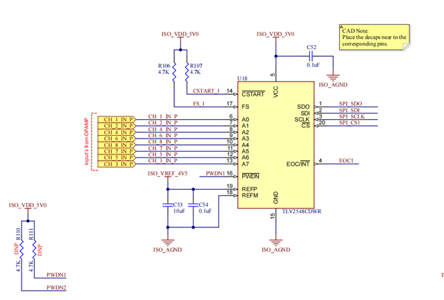
Attaching the Image of Schematics for referece.

  • Hi Alan,

    With FS=1 on the TLV2548, you should be using SPI mode 0, where the clock dwells low and the data is valid on the rising SCLK edge.  Can you send over a screen shot capturing the /CS, SCLK, SDI and SDO lines?  Unfortunately we do not have a LINUX driver to share with you.

  • Hi Tom,

    We solved the issue with the 2 ADC. Now it is working fine.

    Currently we are facing some other issues.

    I will try to explain my circuit in brief,

    we have one processor card and 4 Analog Cards which are connected in a Backplane. In each analog card, we have 2 ADC's communicating through SPI. Also with in each analog card, we have one digital isolator (used for SPI applications) after the ADC's. the voltage is level shifted from 5V-3.3V by the Digital isolator.. After this digital isolator, the SPI lines are travelling through the backplane which is in 3.3V logic and reaches processor card. In the processor card, we have one level translator which translates the logic from 3.3V to 1.8V. Then it is going directly to the processor. This is the Flow of circuit.
    The current Scenario is
    If we are connecting 1 analog card, everything is working fine and we are getting proper reading. the MISO voltage level is also stable.
    if we are connecting 2 Analog cards, The ADC configuration and reading also we are getting. But the voltage level of MISO after the digital isolator( In the Analog Card itself) drops to 2V.
    if we are connecting 3 Analog cards, its somehow working, but cant say a consistency. Here also the MISO voltage level is reduced below 2V( Around 1.8-1.9V).
    If we are connecting 4 Analog cards, it wont work, we didn't get reading from any ADC's even configuration setting also not possible. The voltage level of MISO will drop below 1V.
    We checked all the voltage rails during the SPI communication, We didn't identified any Voltage dip in the power rails. Also the ADC side MISO voltage level is also stable which is 5V. Only after the digital isolator we are facing the dip in the level.
    All the other line except MISO looks ok.

    Attaching the Scope shots of signals after the Digital Isolator. The yellow colured is the MISO, Green-Chip select, Blue- Clock and other one is MOSI

    May i know the possible issue.

  • What is the current rating for the analog card power supply?  If adding cards causes the analog supply to droop, that could be the reason. 

  • The Current rating is below 100mA from 12V. We didnt see any drop in the Analog power supply.

  • If your ISO_VDD_5V0 is stable, then the only other thing I can think of is that somehow you are feeding SDO into a resistive divider or high impedance node.