


Hi team,
One of our customer's issues, I translated it into English as follows, could you please provide some troubleshooting suggestions?
During the DAC38J84 test, there were spurs and harmonics, and the magnitude of the spurs affected the SFDR. Currently, three IF point frequency signals of 60/50/70MHz are output. Scattered points will appear in these frequency points. Through extensive testing, these stray points have a certain regularity. The following figure shows the point at -20MHz frequency offset when outputting at 60M, with a frequency of 40MHz. If the span is set to 200MHz, other harmonics and stray points will be seen. The point that has an impact when outputting at 60M in the following figure is 40M, which has an impact on SFDR exceeding 10dB. Other stray and harmonic signals are far away from the signal, with small amplitudes and little impact. Currently, the main need is to address the stray points at the 20M frequency offset.
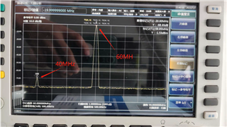
span 50MHZ
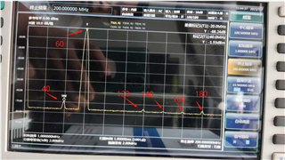
span 200MHZ
The results of measuring multiple frequency points are as follows: (unit: MHZ)
DDS 200Mhz, signal 12.5Mhz
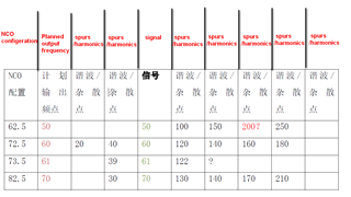 The first column of the table corresponds to the red font I translated.
testing environment
The FPGA outputs a DDS signal with a sampling rate of 200Mhz and a signal of 12.5M. It is fed to the DAC through the 204B interface, and after 4 times interpolation, the DAC is mixed with the internal NCO of the DAC. The mixing uses 800MHz sampling output, and the actual environment is shown in the following figure:
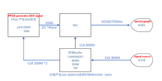
DDS: sampling rate 200 MHZ, signal 12.5MHZ
DAC NCO: see table above
DAC part, DAC38J84
Currently, interpolation filtering, NCO, and QMC are used, while other functions are bypassed
FPGA uses an IP core to generate DDS signals, with a sampling rate of 200M and a signal of 12.5M
Analysis Steps
1. After changing the NCO of DAC and mixing with the 12.5M signal generated by DDS, the stray points will follow the output changes, as shown in the table above
2. Change FPGA DDS=15.625M, NCO=72.5M, and the test results are as follows:

3. DDS output DC component, NCO=72.5M

I am not familiar with DAC38J84. Could you please provide some guidance on problem-solving for this customer
Best Regards,
Amy Luo

