This thread has been locked.

If you have a related question, please click the "Ask a related question" button in the top right corner. The newly created question will be automatically linked to this question.

ADS124S08: ADC doesn't read correct

Part Number: ADS124S08


Hi 

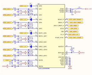
I have ADS124S08 . I use 4 channel. All channels configure with  4 wire pt100.

Some channels read correct, some channels don't read correct.

For example, I measure with multimeter 100.5 ohm 

but when I try with ADS124S08, result is 103.2 ohm

Hardware is correct and I use resistor 1k (%0.001 tolerance).

How can I read correct data?

//U8 data[6]= {0x12, 0x0A, 0x14, 0x12, 0x07, 0xF0}; //Channel 0 configuration

// U8 data[6]= {0x45, 0x0A, 0x14, 0x12, 0x07, 0xF3}; //Channel 1 configuration

//U8 data[6]= {0x78, 0x0A, 0x14, 0x12, 0x07, 0xF6}; //Channel 2 configuration

// U8 data[6]= {0xAB, 0x0A, 0x14, 0x12, 0x07, 0xF9}; //Channel 3 configuration

  • Hi 0_utq_0,

    Can you share the schematic?  The measurement is ratiometric, so how are you making your calculation?  Also, are you taking into account analog settling when switching between channels?

    It would be helpful to see a series of data that is continuous and contiguous (no missing data points for 128 samples) for a single input that you see as not showing correctly.  Here I would like to analyze as raw data (codes) and not converted to resistance.

    Best regards,

    Bob B

  • Hi Bob

    My schematic  is :

    I calculated with below code

    void read_data(ADS124_t* p_ads124,char slaveId, float *data)
    {
        char i_Data[3]={0,0,0};
        unsigned long output_data=0;
        unsigned long  scale = 16777215; //2^24 -1
        unsigned long  gain  = ((2*1000)/4); // (2*RREF) /Gain
        float rrtd=0;
    
        SPI_CS_LO(slaveId);
    
        spiRead(p_ads124->mp_sPI, i_Data, sizeof(i_Data));
    
        output_data = i_Data[0];
        output_data = (output_data<<8) + i_Data[1];
        output_data = (output_data<<8) + i_Data[2];
         
        SPI_CS_HI(slaveId);
        rrtd=(float)output_data/scale;
        rrtd=rrtd*gain;
        *data=rrtd;
    }

    I change channels at 200 ms intervals.

    For example
    I write registers from ADS124S08_INPUT_MUX
    0x12
    0x0A
    0x14
    0x12
    0x07
    0xF0
    and I read first pt100 data.After 200 ms,
    I write 0x45 to INPUT_MAX
    I write 0xF3 to IDACMUX
    and I read second pt100 data.After 200 ms,
    I write 0x78 to INPUT_MAX
    I write 0xF6 to IDACMUX
    and I read third pt100 data.After 200 ms,
    I write 0xAB to INPUT_MAX
    I write 0xF9 to IDACMUX
    and I read fourth pt100 data.After 200 ms, I read first data again.


    Is there a point I missed?


  • Hi 0_utq_0,

    You are using a ratiometric resistance conversion, but it would be helpful to see more than one data point instead of cycling the mux.  If there is analog settling of the input the conversion results will demonstrate this within the results.

    There is a small delay when you switch channels to help with analog settling, but this delay may not be long enough.  When you write a new configuration to the ADC while in continuous conversion mode the conversion will restart, but if the input or reference is still settling then you can read an error. 

    Another thing you could try is to write the configuration then wait 200ms before reading the conversion result instead of waiting after you read the data result.

    On another unrelated issue I see you have a ferrite in the supply line.  I would suggest not using a ferrite as these can often be problematic when the ADC is demanding current for short durations.  Higher current demands take place when starting IDAC currents and turning on the internal reference as examples.  I would suggest replacing the ferrite with a 0 Ohm resistor.

    Best regards,

    Bob B

  • Also row data table  there is a 0.6 ohm difference. When I convert the resistor to temperature, the deviation in temperature is greater.

    Measure with Multimeter Software Raw Data Software Calculated Data
    100.1 0x33d827 100.686
    104.0 0x358ded 104.598
    107.9 0x378dc1 108.503
    111.8 0x398bf0 112.395
  • Hi 0_utq_0,

    This is much different than was originally stated.  The results you are showing appear to be an offset of about 500-600mΩ.  Are you using an actual RTD or a fixed resistor?  How accurate is your multimeter?  If you consistently read an offset you can calibrate this out of the measurement.  First I would suggest that you measure the reference resistor with the multimeter to see if the meter is measuring accurately.  Most likely the reference resistor is not measuring exactly 1000 Ω and any difference will be reflected in the conversion result you are calculating.

    Best regards,

    Bob B

  • Hi Bob

    I use fluke 726 precision calibrator for simulating pt100, yes now 500- 600 mΩ, but  with system integrated, the offset can up to 2 Ω (

    the cable is getting longer).

    I checked reference resistor. It is excatly 1000 Ω.
  • Hi 0_utq_0,

    So are you simulating in 4-wire RTD mode with the calibrator?  If you increase the length of wire, then most likely you are also increasing the length of time for the analog settling as the current flows through the wiring, through the calibrator and back to the ADC.

    And, nothing is exact. Slight smile

    Best regards,

    Bob B