This thread has been locked.

If you have a related question, please click the "Ask a related question" button in the top right corner. The newly created question will be automatically linked to this question.

ADS1231: No data received in DOUT pin of ADS1231

Part Number: ADS1231

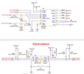
Circuit Description - MCU_ADC_DOUT, MCU_ADC_SCLK is connected to MCU end, and ADC_DOUT, ADC_SCLK is connected to ADS1231 end.

Doubt 1 - I am not getting Data value in DOUT pin. Initially I have configured MCU_ADC_DOUT pin as a GPIO pin to read data. When MCU_ADC_DOUT pin goes low (Data is ready) I will reconfigure this pin as SPI MISO pin to read the converted data. MCU_ADC_DOUT pin is not getting low. I have connected a load cell to ADS1231.

Doubt 2 - Is it necessary for MCU_ADC_SCLK pin to be low initially for MCU_ADC_DOUT to go low.

Doubt 3 - Please check and verify schematic.

Thank You.

Regards,

Neel Madhav

  • Hello Neel,

    The schematic looks correct.  Please confirm that the SPEED pin is driven high or low and that PWDN is driven high.  If these pins are floating, then the ADC may not respond.

    Also, SCLK needs to idle low.  If SCLK is high for more than t-STANDBY (12.5ms, SPEED=1 or 100ms, SPEED=0) then the part will go into standby mode and will not respond.

    Please capture the data on SCLK and nDRDY/DOUT pins using an oscilloscope or logic analyzer to verify timing and proper SCLK operation.  If you post a screenshot similar to Figure 20 in the datasheet, I will review.

    Regards,
    Keith Nicholas
    Precision ADC Applications

  • Hello Keith,

    SPEED pin is HIGH

    PWDN pin is HIGH

    SCLK pin is driven low. At reset due to external pull up SCLK is HIGH. During initialization SCLK is driven low.

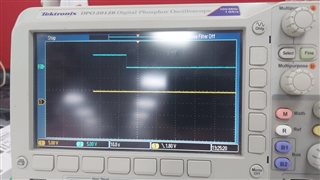
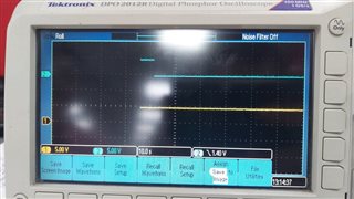
    Screen shots of SCLK and DOUT pin is given below. 

    SIGNAL 1 (YELLOW) - DOUT

    SIGNAL 2 (BLUE) - SCLK


    Code Snippets of initialization- 

    PDWN Initialization - 

    PORTA.ODR1.BYTE |= 0x00;
    PORTA.PMR.BYTE |= 0x00;
    PORTA.PDR.BIT.B7 = 1; 
    PORTA.PODR.BIT.B7 = 1 ; 

    SPEED Initialization -

    PORTA.ODR0.BYTE |= 0x00; 
    PORTA.ODR1.BYTE |= 0x00; 
    PORTA.PMR.BYTE |= 0x00;
    PORTA.PDR.BIT.B6 = 1;
    PORTA.PODR.BIT.B6 = 1; 

    DOUT Initialization - 

    PORT9.PMR.BIT.B2 = 0; 
    PORT9.PDR.BIT.B2 = 0;
    PORT9.DSCR.BIT.B2 = 0;

    SCLK Initialization - 

    PORT9.PODR.BIT.B1 = 0U;
    PORT9.PMR.BIT.B1 = 0U;
    PORT9.PDR.BIT.B1 = 1U;
    PORT9.PODR.BIT.B1 = 0U;

    Application Layer - 

    PortConfiguration();
    while(1) {
     if(PORT9.PIDR.BIT.B2 == 0){ 

    //Switch to SPI }

    Please Check and verify. Issue remains the same "DOUT pin is not getting low after SCLK is driven to low"

    Thank You.

    Regards,

    Neel Madhav

  • Hello Neel,

    Looking back at your schematic, I suggest you change resistor R102 from 47k to 0Ohm on the CLKIN pin.  This pin has an auto-detect feature, and will shut down the internal oscillator if there is noise on this pin.

    In addition, after the power supplies stabilize and after you force SCLK low, I suggest you reset the ADS1231 by pulling nPDWN pin low for a minimum of 26us.  After nPDWN returns high, the DOUT pin should transition from high to low after about 53ms indicating the first conversion result is ready to be read.

    Regards,
    Keith