This thread has been locked.

If you have a related question, please click the "Ask a related question" button in the top right corner. The newly created question will be automatically linked to this question.

ADS8668: SDO problemns in star topology

Part Number: ADS8668

Hello,

1. We are using 2 ADS8668 DACs in star topology. We have 2 separate CS that we control independently and we connect both SDO signals from the 2 DACs together (throug 100R series resistors), I attach the connection diagram. We have encounter SDO problems in this configuration:
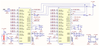
* in one case one of the DACs broke and pulled SDO down continuosuly (we have cheked it by removing the series resistor).

* In other case we have seen that the DACs are not able to carry SDO to 0V, when one of the DACs tried to put a '0' we have measured around 1V, when the other DAC tried to put a '0 we have measured around 2V. In all cases it worked fine for a period of time and start to malfunction after some time working. I attach an oscilloscope capture of this problem.
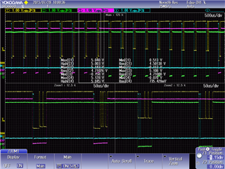
Can you please review the connection diagram and say if we are doing something wrong? Do you have any suggestion?

2. I have also a second question, we have 3k48 resistors in all ain_gnd pins to match impedance. But I have seen in datasheet that direct connection to GND is recommended. Would it be problematic to have it the way we have?

  • Sorry, when I say DAC I want to say ADC....

  • Hi there,

    The 3k48 resistors to ground on the inputs won't have an impact of the SDO.  What else do you have on those lines?  Are you going directly into a micro controller/FPGA?  Schematically, I do not see what might be causing the issue.

  • Hi, I'm Marina's colleague.
    The SPI lines all go to isolators and then to an FPGA. The SDO line has pull-ups before and after the isolator.
    Besides the 2 problems reported by Marina, we see one more: The SDO line keeps low when CS is disabled, but it does get to 1 when communicating. Actually the data it reports is correct, but when chipselect is disabled the SDO remains low. Can it be maybe that the chipselect signal is internally stuck at 0? Would it behave this way in such case?

  • The problem I'm describing happened in one board only, and it was working normally at first and started failling eventually. Once it started failing it always behaves as described.

  • Hi Xabier,

    If the /CS were somehow damaged inside the chip, SDO would follow whatever state the LSB was in.  If the LSB from the conversion process happened to be '1', the output would continue to drive a '1'.  Can you open R11 and/or R15 and probe SDO directly at the chip?

  • Sorry, I forgot to mention that in the board we see this behavior we have separated both SDO to check which ADC was pulling it low, and we see that only one of the ADCs is behaving this way, the other one works correctly. Having the SDO lines separated I see that the data they report is correct, even though one of them keeps SDO low after its CS goes high. The problem is we check the status of SDO when CS is disabled in order to detect if SDO gets stuck at 0, so even though the reported data is correct, we detect an error and can't rely on the data.

  • Is this just an issue with one PCB or have you seen it across multiple boards?  I suspect somehow this particular device got damaged, perhaps through an ESD event?  Can you put a zero ohm resistor in place of L5 between GND_A and GND_ISOL to see if that has an impact?

  • What we have seen repeated in at least 8 boards (we are stlll prototyping so that's almost all of the baords we've got) is that at some point the check for SDO=1 while /CS=1 fails.
    In most cases the problem appeared at room temperature, within minutes. However in 3 different boards they worked fine at room temperature and the problem happened when testing it at 70ºC. In most cases problem dissapeared once rebooted and never happened again, even if we tried stressing it further with hotter temperatures (that's why we have not been able to debug de issue properly)

    In only one board have we seen with the oscilloscope that SDO remains at 0 when /CS goes high, but gets to 1 properly during communication (and as I said, this board worked fine at first, started failing sporadically at 70ºC testing and nowo it always fails).

    In only one other board have we seen with the oscilloscope that the SDO levels are wrong (1V-2V) and this board was thouroughly being tested so it could be that in one of the tests something was damaged.

    In only one other board have we seen that the SDO remains stuck at 0, and again, at first it worked fine, it then started behaving like this after 70ºC testing.

  • Very strange Xabier.  If it is OK with you, I'll contact you through your profile e-mail to get more details.

  • Hi Tom,
    Finally got around this problem: we shorted L5 (the ferrite separating AGND and DGND) and problem solved!
    As I said, the problem seemed to happen only once in each board, and after a reboot we couldn't reproduce it, so we first tried by desoldering the ADCs and putting new ones, and then the problem did happen again, so we knew it was only related to the ADCs, and there was nothing in the other components involved.

    I still don't understand how that ferrite ends up causing such trouble, I don't think it made the difference betweem AGND and DGND  >0.3V.
    Anyway, I would recommend you to add a statement in the datasheet recommending to use the same GND for both AGND and DGND, because at least for me, having them with a different name encourages to separate them to make the analog one cleaner.

    Thanks for your help and best regards!

  • Great news!  Thank you for letting us know - I'll see what updates we can make in the datasheet.