This thread has been locked.

If you have a related question, please click the "Ask a related question" button in the top right corner. The newly created question will be automatically linked to this question.

ADS8588H: Offset error explanation

Part Number: ADS8588H

Hi,

I am doing a tolerance Calculation of a circuit using this ADC. It seems, that the offset error is dominating my tolerance.

I interpret the value of +/-3mV (both ranges) as maximum over operating temperature (-40°C to 125°C)

As my design would not see that high temperatur range, I think, I can use a smaller min/max value when I it calculate with the offset error temperature drift of +/- 3ppm/°C.

But I don't know how to calculate it.

Or more precice, when 3ppm is the same as 0.0003%, what is the value of 100%.

  • Hi Sebastian,

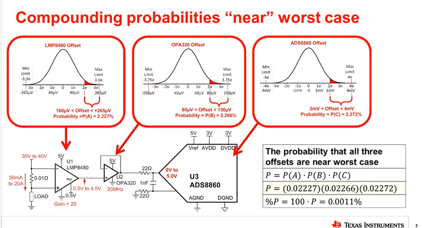
    I always recommend calculating typical error and maximum error separately as maximum error might be statistically unlikely for you system. It becomes even more unlikely has you stack multiple maximum errors together:

    More information can be found in the Precision labs video on Error sources and the video titled - Statistics behind error analysis of ADC system : https://www.ti.com/video/series/precision-labs/ti-precision-labs-analog-to-digital-converters-adcs.html 

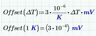
    Anyways, the ppm is in reference to original unit, so mV. That means for 1C change, output should change by a maximum 3/1,000,000 mV = 3*10^-6 mV. This is true when see other ppm/C type drift specifications, like resistance or voltage outputs.

    Best,

    -Cole

  • Hello Cole,

    for tolerance analysis we use the so called "One at a Time" method with the worst case values. https://en.wikipedia.org/wiki/Sensitivity_analysis#One-at-a-time_(OAT) 
    The total error is then calculated by RSS of each single parameter influence. This introduces the statistical distribution into the final result (so was it told to me...). 

    According the offset Error and its drift:
    I still assume, that the maximum Offset and drift over the whole Temperature range is +/-3mV resp. +/-3ppm/°C. The precision lab videos told me, that it could also be the production test limit and the gaussian distribution is truncated.
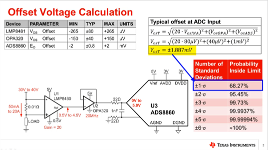
    And the video told me, that the typical limit (+/-0.2 mV @ Range +/-10V) is the gaussian distribution of +/-1sigma (in the ADC datasheet the typical values are at 25°C)

    When I now want to calculate a temperature dependent offset according your given fomula. The result at the operating temperature limits are not even near the maximum value.

    I did this calculation with Mathcad. It transferes °C into K. Therefore every "delta Temperature" is in K.

    Definition of the formula and check against your explantion:
     the same value as your explanation.

    Calculation of the temperature changes with operating maximum:

    Calculation of the tempearture dependent offset and adding to the typical value

     I didn't expect to hit +/-3mV, but I didn´t expect to be factor ~15 away.
    Am I missing something? 

  • Hi Sebastian,

    The total error is then calculated by RSS of each single parameter influence. This introduces the statistical distribution into the final result (so was it told to me...). 

    This is correct! Root Sum of Squares for uncorrelated error is how you put all the error together.

    I'd watch the next video on offset too if you haven't. While +/-1 std dev encapsulates the typical value, as you move bounds out to the maximum it may or may not reflect the 3 or 4 std. dev of all devices. So, you compare the typical value to the max and the max is less than 3 or 4 std, then you can assume we put limits. Otherwise, everything is guassian so you can 

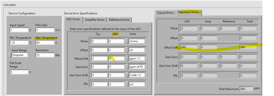
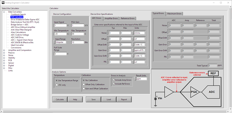
    I don't follow your math but we have a calculator that can do the calculations for you. You should type your values into the calculator and compare your calculations with mathcad if you'd like. You can find the link to the calculator here:

    The hard part is making sure you do the units correctly but it has ppm / C on the GUI so you should be good.

    Best,

    -Cole

  • Hello Cole,

    I installed the calculator, and at first, I was totally confused, because the error is given in ppm. Where I again was missing the reference of it.

    But the help showed me, that it refers to Full_Scale_Range.

    so also the resulting ppm has to be related to full scale.

    That raises the question for me, what value to use for full scale 5V, 10V or 20V?
    And why is the maximum value of both ranges the same value (in the datasheet)?

    Although the calculator let me insert a maximum Value for the error Specification, it has no influence to the calculation. For me, a total maximum dependent of the temperature would be interesting.

  • Hi Sebastian,

    That raises the question for me, what value to use for full scale 5V, 10V or 20V?

    I would read this blog about converting from code to voltage and the explanation of the FSR.

    Essentially, RANGE determines what the range is, and because this is a bipolar input, you'll be able to put m = 2, into that equation so your two options are 10V (+/-5V) or 20V (+/-10V)

    The real issue is, we don't say what gain or the reference voltage is, we just say +/-10V or +/-5V. So, I would recommend just inserting the values in or figuring them out by assuming the correct behavior by looking at the datasheet. 

    And why is the maximum value of both ranges the same value (in the datasheet)?

    So this is what the equation is trying to say. It is a bit confusing but we're trying to normalize everything to the actual output range that can be measured. So, if the maximum voltage we can measure is 10V and we have a G = 2, the new and real voltage maximum is actually 5V. It turns into a "how do we represent this" type of question. Do we say "your output error is 20mV in G =2 and 10mV in G =1" or do we say "this is input referred at it is just 10mV, you'll have to do the math on the actual gain you have to get the actual output error".

    We went with the 2nd method. 

    Although the calculator let me insert a maximum Value for the error Specification, it has no influence to the calculation. For me, a total maximum dependent of the temperature would be interesting.

    Did you click the tab for maximum? Playing around with your min and max temperature with drift values inserted will change the maximum.

    Going back to the beginning. Its always good to compare your typical error to the maximum error.

    Best,

    -Cole

  • Hi Cole,

    I did not click the maximum tab...
    I don´t know why or how I missed that... Thinking
    Sorry.

    With the maximum tab, I found out, that the calculator does the same than we do.

    I think one has to be carful when using the calculator with maximum error.
    In my opinion, when the maximum offset error is over the whole temperature range, this value is including the offset drift over temperature too.
    So adding the maximum drift (from the maximum temperature delta) to the maximum offset would be way too worse.

    Anyway, thank you very much, for your explanations.

    For me the topic is closed.

    Regards
    Sebastian