This thread has been locked.

If you have a related question, please click the "Ask a related question" button in the top right corner. The newly created question will be automatically linked to this question.

ADS8201: Read and Write Issue.

Part Number: ADS8201

Hi All,
Now, I use ADS8021 to read ADC values by SPI communication.

Do the Below Steps for Configuration Ic.

  1. Write 0x00 to reg 0x08 > Ads8201_SetAdcTriggerScr(ADC_IDEL);
  2. Write 0x00 to reg 0x04 > Ads8201_ChannelSelection(CHANNEL_0);
  3. Write 0x00 to reg 0x05 > Ads8201_SetAdcScr(NO_AVERAGE, EDGE_TRIGGERED, ACTIVE_LOW, INT, FIFO_BUFF_ENABLED, CONVERT_START_THROUGH_SPI);
  4. Write 0x02 to reg 0x06 > Ads8201_SetInterruptScr(DISABLE_INTERRUPT, ENABLE_INTERRUPT, DISABLE_INTERRUPT, DISABLE_INTERRUPT, DISABLE_INTERRUPT);
  5. Write 0x05 to reg 0x08 > Ads8201_SetAdcTriggerScr(AUTO_TRIGGER_AUTO_CHANNEL_UPDATE_SINGLE_SCAN);
  6. Write 0x00 for Read ADC > Ads8201_SpiRead(Add, &data, sizeof(uint8_t));
    I did not Get Any data on the MISO pin.

The SPI Mode is set 1 (CPOL = 0, CPHA = 1).

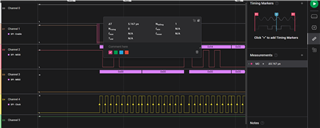
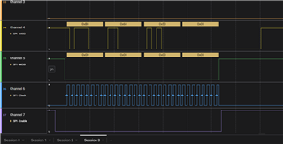
PFA for cycle
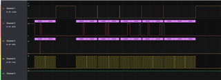

Anyone know sequence to read adc value(configure + read)

Thanks and best regards.

  • Hi Vrushal,

    What is the timing of your sclk?  I can't see what your timebase is in the screen shot you captured.  What is the high time of /CS between the tranmit packets?  Why is the time between 8-bit packets short?  Can you include the BUSY signal in your LA capture?

  • Hello Tom,

    Thanks For the Replay.

    Clock Freq is 1 MHz. 

    The high time of  /CS between the transmit packets is 5.167 uSec.
    SPI configuration is control is 8 Bits per frame sent.
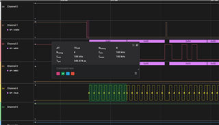
    PFA for Your Reference. 
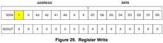
  • Can you please include the CONVST and BUSY signals?  Can you also try reading back register details to confirm your communication is getting received correctly?  I do not see where you are setting the MSB indicating a register write operation:

  • Hi Tom

    Hi Tom,

    I do the below step for configuration.

    Write 0xA000 for select ADEL MODE in ADC Trigger SCR reg.
    Write 0x9000 for Channel 0 Selection.
    Write 0x9413 for NO_AVERAGE, EDGE_TRIGGERED, ACTIVE_LOW, INT, FIFO_BUFF_ENABLED, CONVERT_START_THROUGH_SPI in ADC SCR reg.
    Write 0x9802 for Enable Int for scan data Ready in Interrupt SCR reg.
    Write 0xA006 for Auto Trigger Auto Channel update Multi Scan in ADC Trigger SCR reg.

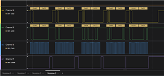
    After Reading ADC Data, I did not get the proper value.  Also, do not update the channel number in the following sequence reading. Every reading sequence data is the same. 0xB86050
    How do I get ADC data from channel 0?
    Thanks and best regards.
  • Can you please include CONVST and BUSY?