This thread has been locked.

If you have a related question, please click the "Ask a related question" button in the top right corner. The newly created question will be automatically linked to this question.

AMC1305L25-Q1: technical consult

Part Number: AMC1305L25-Q1
Other Parts Discussed in Thread: AMC1305M25
  • Actually, there is an application project where we use TI Chip AMC1305L25-Q1 whose datasheet is attached.
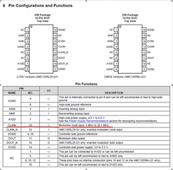
  • We have a question about pin13 CLKIN that request 5MHz to 20.1MHz for usage as below shown in datasheet, however, due to device limitation from VT, we’d like to use 1MHz for testing.
  1. Is the functionality of chip available or not if we trigger test with 1MHz to pin13 CLKIN?
  2. What’s risk can you see from chip point of view if so?
  3. amc1305m25-q1.pdf
  • Hi Chenyang,

    Thanks for your question. I assume providing a clock of less than 5MHz may lead to incorrect/no DOUT and the datasheet device specifications may not be met as you would be operating outside of recommended conditions. We recommend using at least 5MHz CLKIN as that is what this device is specified for. But, I will try providing a clock of 1MHz on my end and check to see what the behavior is like and get back to you.

    Best,

    Samiha

  • thank you for your prompt response.

    Actually, we tried testing DOUT with 1MHz, the DOUT wave status is almost same with 5M/10M/20M, this is why I raise this question. 

    for sure, I am looking forward to your test results and further comments.

    additionally, when shall I get the result from your side?

  • Hi Chenyang,

    I'll get back to you later today!

    Best,

    Samiha

  • Hi Chenyang,

    Thanks for your patience. We took a look at the DOUT at 1MHz CLKIN. It seems to be functioning as usual, as you saw as well. So that's good. However, you may begin to see issues as you operate over temperature. It is difficult to predict or guarantee device behavior when operating outside of recommended conditions.

    I hope that helps!

    Best,
    Samiha 

  • Hi, Samiha,

    Thank you for your great effort, it is good having such info.  what's more, I have some other concern.

    Q1: Additionally, how do you define parameter scope in datasheet generally? could you give me some explanation if it is not confidential.

    Q2: I assume that's set by typical application testing, did you test with outside of recommended condition under all temperature scope? as this is very valuable for me, so can you share some information to me?  thank you in advance.

    Q3: the last but not least, in other words, could TI commit to accept this kind of failure sample with 1M clock testing that is offline from production line? 

    It‘s apricated to have your reply as soon as possible, have a nice weekend. 

    Best,

    Chenyang.

  • Hi Chenyang,

    The conditions the device specifications are noted for are shown on top of the Electrical Characteristics table, for example right under the Section 7.10 heading in the datasheet.

    The temperature range the part is specified for is -40C to 125C as shown in table 7.3.

    I don’t fully understand your last question but we recommend using the device at CLKIN speeds recommended in the datasheet: 5MHz to 20.1MHz, to ensure device performance is as expected.

    Best,

    Samiha