


Other Parts Discussed in Thread: ADC12QJ800
We are currently in the process of developing a new data acquisition system for one of our products using the ADC12QJ800
interfaced to the TI-JESD204 IP modified from the zcu102 reference design to suit the Kria K26 SOM being used for our project.
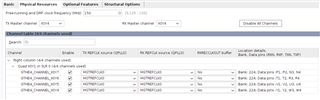
I have managed to configured the ADC and JESD IP to run 4 channels at 800MSps with 12bit ADC resolution. The JESD_Status from the ADC SPI Commands show Link is up, but when i release the JESD resets it doesn't always give a lemc to buffer release value. I have already set an appropriate buffer release delay. After some consecutive resets I get the lemc to buffer release and some valid clocks with x amount of data before it stops. This is all happening before the ILA can capture another valid signal so not long. There are some CRC errors I get from time to time and I have run a ramp test pattern and it seems that I only get a couple glitches in my data some times. I would like to know how to go about debugging this issue and resolving it so I can get a reliable link that can transmit data 24/7. I am not sure if its just a synchronization issue and I am missing something or data integrity issues due to board layout. lemc pulse aligns to sysref and seems to continue regardless of valid data and seems to produce and accurate period from all my calculations.
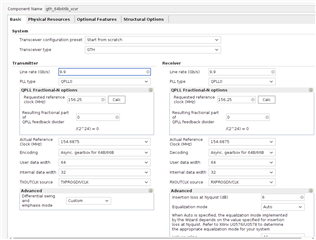
ADC has been configured to use the differential clk pins with a 100MHz reference clock generated on board locally to the ADC. PLLREFO then passes that clock to the FPGA to generate the drp freerunning Linerate/66=150MHz clock for the JESDIP/Tranciever and FPGA device clock at 200MHz that is sampled down to produce a 312.5KHz sysref. Trigout is programmed for Linerate/32=309.375MHz into the GTH Reference Clock.
ADC Calculations
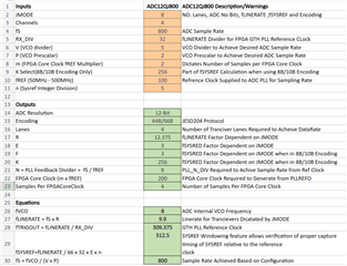
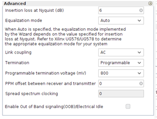
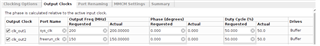
GTH Tranciever Settings
MMCM Clock Configuration

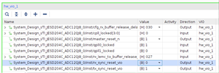
VIO
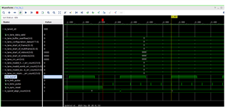
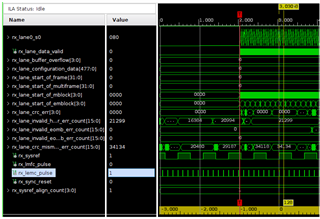
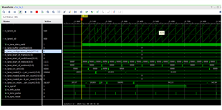
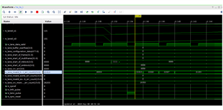
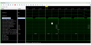
ILA Trigger on Reset
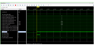
ILA Trigger on Data Valid
SPI Code to ADC
//Soft Reset
spi_data = ADC_WriteRegister(ADC_CONFIG_A,0xB0,1);
xil_printf("Soft Reset ADC12QJ800\r\n");
//Wait for INIT_DONE
spi_data = 0;
while(spi_data == 0){
usleep(100000);
spi_data = ADC_ReadRegister(ADC_INIT_STATUS,1);
xil_printf("INIT_STATUS:0x%x\r\n",spi_data);
}
//CPLL Configurations
ADC_WriteRegister(ADC_CPLL_RESET ,0x01, 1);//reset CPLL
ADC_WriteRegister(ADC_CPLL_VCOCTRL1,0x4A, 1);//VA11Q & VCLK11 Noise Suppresion
ADC_WriteRegister(ADC_CLK_CTRL0 ,0xE7, 1);//SYSREF_PROC&RECV_EN SYSREF_SEL=7
ADC_WriteRegister(ADC_CLK_CTRL2 ,0x05, 1);//CPLL VCO_BIAS
ADC_WriteRegister(ADC_CPLL_FBDIV1 ,0x04, 1);//VCO/(PxV)=800MHz (P=2 V=5)
ADC_WriteRegister(ADC_CPLL_FBDIV2 ,0x08, 1);//Fs/Ref=800MHz/100MHz (N=8)
ADC_WriteRegister(ADC_VCO_CAL_CTRL ,0x41, 1);//VCO_CAL_EN
ADC_WriteRegister(ADC_CPLL_RESET ,0x00, 1);
//Stop JESDC
ADC_WriteRegister(ADC_JESD_EN ,0x00, 1);
ADC_WriteRegister(ADC_CAL_EN ,0x00, 1);
ADC_WriteRegister(ADC_JMODE ,0x08, 1);//JMODE8
ADC_WriteRegister(ADC_JTEST ,0x04, 1);//Ramp Test Data
ADC_WriteRegister(ADC_JCTRL ,0x0B, 1);//JSYNC_N Signed 2’s Scramble
ADC_WriteRegister(ADC_TRIGOUT_CTRL ,0x82, 1);//TRIGOUT 9.9Gbps/32=309.375MHz
ADC_WriteRegister(ADC_OVR_CFG ,0x0F, 1);//OVR_EN 512samples
//Wait for VCO_CAL_DONE
spi_data = 0;
while(spi_data == 0){
usleep(100000);
spi_data = ADC_ReadRegister(ADC_VCO_CAL_STATUS,1);
xil_printf("VCO_CAL_STATUS:0x%x\r\n",spi_data);
}
//Wait for CPLL_LOCKED
spi_data = 0;
while(spi_data == 0){
usleep(100000);
spi_data = ADC_ReadRegister(ADC_JESD_STATUS,1);
xil_printf("ADC_JESD_STATUS:0x%x\r\n",spi_data);
spi_data = spi_data & 0x01;
}
//Enable JESD204C
ADC_WriteRegister(ADC_CAL_EN ,0x01, 1);
ADC_WriteRegister(ADC_JESD_EN ,0x01, 1);
ADC_WriteRegister(ADC_ALM_STATUS ,0x3F, 1);//Clear Alarm
ADC_WriteRegister(ADC_CAL_PIN_CFG ,0x00, 1);//FG_DONE,CAL_PIN_CFG
ADC_WriteRegister(ADC_CAL_SOFT_TRIG ,0x00, 1);
ADC_WriteRegister(ADC_CAL_SOFT_TRIG ,0x01, 1);//Initiate Calibration
//Wait for FG_DONE
spi_data = 0;
while(spi_data == 0){
usleep(100000);
spi_data = ADC_ReadRegister(ADC_CAL_STATUS,1);
xil_printf("FG Calibration Done:0x%x\r\n",spi_data);
spi_data = spi_data & 0x01;
}
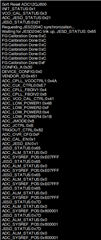
ADC Debug SPI Status
I have tried configuring different Test Modes some work a little more reliably than others and I have also tried configuring for 500MSps with similar results, but regardless if the error seem less the I never seem to get more than the first group of data and it stops. When using SerDes Pre-emphasis things seem to get worst, I have also tried playing with the GTH Insertion Loss, but It doesnt seem to make to much of difference as far as making it any better. I have also tried 100,200 and 300 ppm offset, but these also I think made things worse so I have left it at 0.
Is there anything you could suggest to help understand the errors that I am getting and how to resolve the link to get a continuous stream?
Thankyou in advance.
