This thread has been locked.

If you have a related question, please click the "Ask a related question" button in the top right corner. The newly created question will be automatically linked to this question.

DAC8760: DaisyChain Communication with CRC

Part Number: DAC8760

After implementing CRC in all our devices utilizing eight DAC8760 units in a daisy chain configuration, we continue to experience long-term stability issues. It appears that our daisy chain intermittently "breaks" at unpredictable intervals, ranging from 5 days to 30 days, rendering all subsequent DACs inoperative until a power cycle and re-initialization occur.

We have refrained from enabling the watchdog function, and we are also not actively monitoring the alarm pin or the corresponding register.

Could you kindly provide clarification on the following points:

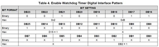
  1. If the watchdog feature is enabled randomly on one or more DACs by the mentioned bit-pattern-bug, should this result in any changes in the mA output behavior or stop it?

  2. In the event of an alarm being triggered, regardless of its cause, should this result in any changes in the mA output behavior or stop it?

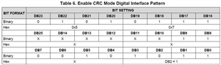
  3. Is there a possibility that CRC functionality could be also disabled by a specific bit-pattern without pulling the Latch?

  4. What precisely does the NO OP command to the CRC calculation? Shouldn't a full daisy chain data transmission (comprising 8 times 32 bytes in our setup) serve the same purpose of resetting the "SPI counter," whatever that means?

Urgent assistance is imperative, as we remain unaware of the potential number of devices deployed in sensitive areas that could abruptly cease updating their mA outputs. We are perplexed as to the root cause of these occurrences.

It is especially distressing since this marks the second occasion we have had to do debugging for weeks. On the previous instance, we found out about the CRC bug by sheer luck and subsequently painstakingly distributed firmware updates enabeling CRC communication to all our deployed devices across the globe.

We appreciate your prompt attention to this matter.

  • Hello,

    For context on this issue, let me give a little background for other readers of this post. We had made a change to the datasheet about two years ago to remove the daisy chain mode as a recommended mode of operation.

    As we had mentioned in the previous revision of the datasheet (in sections 8.3.9.1 and 8.3.10.1) there may be specific bit patterns that can erroneously cause the watchdog timer or the CRC to be enabled without a rising edge of the LATCH pin. These bit patterns were shown in Table 4 and Table 6 of the previous revision of the datasheet:

    Further, we were concerned that with the use of the daisy chain, there may be a chance that this digital pattern could be seen through the course of sending multiple commands to multiple types of devices sharing the SPI. This would accidentally enable the CRC or set the watchdog timer.

    In the end we chose to remove the daisy chain from the datasheet. It is easier to use the device with a controller that can handle independent sets of SPI, or use parallel SPI lines with separate /CS selections and a gated SCLK. The change in the datasheet was not because of a change in the device. The device has remained the same since its introduction in 2013. For existing customers that use daisy chain, they could continue to use it. 

    As for your questions, here are some answers. 

    1. The watchdog feature by itself does not trigger extra changes in the output current (or from the current from the device). The watchdog itself is implemented in the digital section as a timer from the device's clock, waiting for digital communication.
    2. When the alarm is tripped, the status register fault flag corresponding with the device output is set. The DAC output does not change. The only change would be the /ALARM pin being pulled low in response to the alarm. This would increase the device current because the /ALARM pin requires a pull-up resistor.
    3. I don't think that the CRC could be disabled in a similar method. Based on my understanding of this problem, the accidental enabling of the CRC puts the device into a mode where the CRC cannot be enabled or disabled through writes to the configuration register. Also, the alarm pin and status register do not indicate the CRC alarm conditions, and frames with incorrect or missing CRC bits are not disregarded. I'm checking with one of the digital designers to confirm this.
    4. I'm not sure I understand this question. Does this refer to sending a NOOP command to reset the SPI clock and frame in the device (at the end of page 33 of the datasheet)? For the NOOP, this was intended to align the SPI frame in the event that any transients on the SCLK line are interpreted as SCLK periods. I don’t have any specific knowledge as to why this was inserted into the datasheet, but I don’t think that this absolutely needed. The frame should be aligned after a correct SPI command.

    I’ve requested E2E friendship, so that we can send messages to each other. I think this will a faster method for communicating this than through E2E posting.


    Joseph Wu