This thread has been locked.

If you have a related question, please click the "Ask a related question" button in the top right corner. The newly created question will be automatically linked to this question.

ADC32J25: ADC32J25: JESD204B Configuration (Part 2)

Part Number: ADC32J25
Other Parts Discussed in Thread: LMK04828,

Hello,

I'm including the previous thread here for background.

ADC32J25: JESD204B Configuration - Data converters forum - Data converters - TI E2E support forums

Also attached are

  1. TICS Pro file for LMK04828
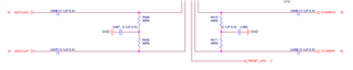
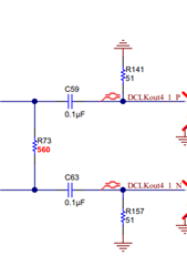
  2. Schematic 
    1. LMK04828 circuit is on Sheet 18
    2. ADC32J25 circuit is on Sheet 15
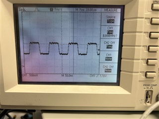
  3. Photos of SYSREF outputs
    1. SDCLKOUT1_sysref.jpg: sysref signal that goes to the FPGA
    2. SDCLKOUT3_sysref.jpg: sysref signal that goes to the ADC
  4. FPGA capture
    1. the waveform is continuous for 32 samples and goes thru a jump
    2. F=2 and K=32.  Is there any conflict with SYSREF = 8 MHz (20x_?

Issues

  • SDCLKOUT3 looks like a constant voltage at 2 volts.  There is no 8MHz sysref observed.
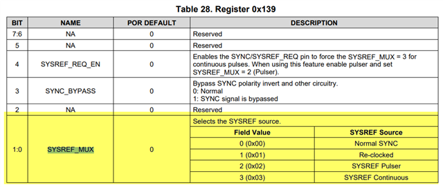
  • SDCLKOUT1: I changed  to 0x139[1:0] = 00 from 11 but the sysref is still repetitive at 8MHz.

We have verified sending the commands to the ADC and the FPGA is working.

  • We can read back the ADC commands.  We can make changes and the read back shows correctly
  • LMK04828: DCLKOUT12 and SDCLKOUT13 are brought out to MMCX connectors for monitoring purpose.  We can change the frequency from 160 MHz to 10 MHz or other frequency.

Could you advise on the issues with the SYSREF?

  • no clock/pulse on SDCLKOUT1
  • not being able to change to one-time on SDCLKOUT3)

Regards,

Andrew

tics_pro_v090823a.tcs

8625.fibersense_v1p23.pdf

  • Hi Andrew,
    To test your config I will need to rework EVM given input isn't supported by onboard VCXO. 

    I'll update you accordingly. 

    Regards, 

    Vicente 

  • Hi Andrew, 
    I was able to successfully see a continuous 8 MHz SYSREF output on SDCLKOUT1 & SDCLKOUT3 using config you provided after reworking LMK04828EVM. 

    I also changed SYSREF mode Pulser Mode: This results in SYSREF_ MUX (R313) = SYSREF PULSER (0x02) & SYNC_MODE = SYNC Pin (Pulser)

    You must also set SYSREF_PULSR_PD from H -> L 

    I set SYSREF_PULSE_CNT = 1 and observed a single pulse for both SDCLKOUT1/3 every time I clicked "send pulses" button in TICSpro GUI. 

    From schematic please note 100 ohm differential termination should be near Tx side before AC coupling caps. 

    One question - what is purpose of these 75 Ohm Resistors? 

    Regards, 

    Vicente

  • HI Vicente,

    Would you review the .tcs attached here?

    I am still getting the continuous sysref.

    As for 75R, I'm also trying to track down the rationale.

    Thanks again for your support

    Regards,

    Andrew

    tics_pro_v092523b.tcs

  • Hello Andrew,

    After loading the .tcs file you attached (attached below), the SYSREF_MUX is still set to continuous, which is why you are still seeing a continuous 8-MHz SYSREF signal.

    To change it, select the value of 0x139[0:1] to your desired SYSREF_MUX state. Note that the SYSREF_MUX state is the type of SYNC signal that you want to pass that resets your dividers and phase aligns your outputs.

    Let me know if I have missed any other questions you have.

    Good luck,

    Andrea

  • Hi Andrea,

    Can you load the attached tcs file below?

    It does clearly shows SYSREF Pulser.

    And the exported register shows 0x013902.

    However, the SYSREF received by the FPGA is still continuous.

    Is there another register that needs to be set to enable the pulse sysref?

    Regards,

    Andrew

    tics_pro_v092623a.tcs

    R0 (INIT)	0x000090
    R0	0x000010
    R2	0x000200
    R3	0x000306
    R4	0x0004D0
    R5	0x00055B
    R6	0x000600
    R12	0x000C51
    R13	0x000D04
    R256	0x01000F
    R257	0x010155
    R258	0x010255
    R259	0x010301
    R260	0x010422
    R261	0x010500
    R262	0x010670
    R263	0x010711
    R264	0x01080F
    R265	0x010955
    R266	0x010A55
    R267	0x010B00
    R268	0x010C22
    R269	0x010D00
    R270	0x010E70
    R271	0x010F66
    R272	0x01100F
    R273	0x011155
    R274	0x011255
    R275	0x011300
    R276	0x011402
    R277	0x011500
    R278	0x0116F0
    R279	0x011711
    R280	0x01180F
    R281	0x011955
    R282	0x011A55
    R283	0x011B00
    R284	0x011C02
    R285	0x011D00
    R286	0x011EF0
    R287	0x011F17
    R288	0x012018
    R289	0x012155
    R290	0x012255
    R291	0x012300
    R292	0x012402
    R293	0x012500
    R294	0x0126F1
    R295	0x012711
    R296	0x012808
    R297	0x012955
    R298	0x012A55
    R299	0x012B00
    R300	0x012C02
    R301	0x012D00
    R302	0x012EF9
    R303	0x012F00
    R304	0x01300F
    R305	0x013155
    R306	0x013255
    R307	0x013300
    R308	0x013422
    R309	0x013500
    R310	0x0136F0
    R311	0x013766
    R312	0x013805
    R313	0x013902
    R314	0x013A01
    R315	0x013BE0
    R316	0x013C00
    R317	0x013D08
    R318	0x013E00
    R319	0x013F00
    R320	0x014000
    R321	0x014101
    R322	0x014200
    R323	0x014311
    R324	0x0144FF
    R325	0x01457F
    R326	0x014600
    R327	0x01471A
    R328	0x014802
    R329	0x014942
    R330	0x014A02
    R331	0x014B16
    R332	0x014C00
    R333	0x014D00
    R334	0x014EC0
    R335	0x014F7F
    R336	0x015003
    R337	0x015102
    R338	0x015200
    R339	0x015300
    R340	0x015478
    R341	0x015500
    R342	0x015664
    R343	0x015700
    R344	0x015896
    R345	0x015900
    R346	0x015A64
    R347	0x015BD4
    R348	0x015C20
    R349	0x015D00
    R350	0x015E00
    R351	0x015F0B
    R352	0x016000
    R353	0x016101
    R354	0x016225
    R355	0x016300
    R356	0x016400
    R357	0x01650F
    R369	0x0171AA
    R370	0x017202
    R380	0x017C15
    R381	0x017D33
    R358	0x016600
    R359	0x016700
    R360	0x01680F
    R361	0x016959
    R362	0x016A20
    R363	0x016B00
    R364	0x016C00
    R365	0x016D00
    R366	0x016E13
    R371	0x017300
    R386	0x018200
    R387	0x018300
    R388	0x018400
    R389	0x018500
    R392	0x018800
    R393	0x018900
    R394	0x018A00
    R395	0x018B00
    R8189	0x1FFD00
    R8190	0x1FFE00
    R8191	0x1FFF53
    

  • Hi Andrea,

    What voltage type should be used for the ADCCLK and SYSREF?

    The ADC also has AC caps and 100 Ohm across the P/N pins.

    Initially I used LCPECL on both but SYSREF did not show a signal.  

    So updated to LVDS and can observe the SYSREF showed the correct clock frequency (5 MHz in the particular case).

    Regards,

    Andrew

  • Hello Andrew,

    I downloaded your newest file and that one did show SYSREF Pulser.

    Is there another register that needs to be set to enable the pulse sysref?

    Yes, I just realized you were setting the SYNC_MODE register incorrectly. Set register 0x143 = 13. This allows you to get the pulser signal from the SYNC SPI command. I have attached this .tcs file below (sorry for not attaching the one I used yesterday to that reply).

    4828_SYSREF_Pulser.tcs

    If you want to obtain the pulser signal from the SYNC Pin, then set 0x143 = 12.

    What voltage type should be used for the ADCCLK and SYSREF?

    The common mode voltage of the ADC32J25 is 0.95-V with the below amplitudes for each clock format. In general, ADCs can accept LVDS, LVPECL, and CML from TI's clocking devices.

    So updated to LVDS and can observe the SYSREF showed the correct clock frequency (5 MHz in the particular case).

    LVDS is an accepted signal to the ADC based on it's swing characteristics, so using LVDS will work. However, form the picture above, you have terminated the LMK outputs as LVPECL outputs. I would suggest to change the SYSREF outputs to LVPECL, and if you still encounter a problem, make sure to have any LVDS outputs from the LMK to match the following topology:

    Hope this helps and let me know if you need anything else.

    Good luck,

    Andrea

  • Hi Andrea,

    The SYSREFs are still continous.

    Could you take a look at the attached .tcs?

    Regards,

    Andrewtics_pro_v092723a.tcs

  • Hello Andrew,

    I was able to get the Pulser mode with your same config except setting 0x143 = 13 to set the pulser in to be sent via SPI (which is the mode I prefer), is there a reason why you are using the SYNC Pin? Also, to sent the pulses via SPI, all you need is to send the command 0x13E = 0 and the pulse(s) should be sent. Please find the waveform I saw on the scope below and the config I used:

    4828_SYSREF_Pulser_9-28.tcs

    Let me know if you have any other questions.

    Good luck,

    Andrea