This thread has been locked.

If you have a related question, please click the "Ask a related question" button in the top right corner. The newly created question will be automatically linked to this question.

ADS127L01EVM: No data detected via SPI with 500kHz

Part Number: ADS127L01EVM
Other Parts Discussed in Thread: ADS127L01

Hi Team,

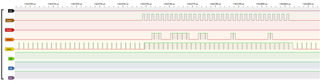
My customer have done some of the testing (SPI with 500khz SCLK) while they found out that sometime there are no data sent from TI ADS127L01EVM to MCU.

These “no data sent” issues usually will happen one or two times in between.


Please look at the picture attached below:


No data issue picture:

Please advise. Thanks!

Best Regards,

Ernest

  • Hello Ernest,

    The data rate of the ADS127L01 is too high for a 500kHz SCLK.  You can determine the data rate by measuring the /DRDY period, which is operating at 500kHz.  At this rate, the minimum SCLK frequency needs to be approximately 40x higher, or 20MHz in this case.  If the customer wants to operate at 500kHz SCLK frequency, then the data rate needs to be reduced to 12.5kHz or lower by adjusting the OSR and filter settings.

    In addition to the proper clock frequency, the MCU needs to monitor the status of the /DRDY pin (can use an interrupt) and when /DRDY goes low, transfer the data, leaving at least 4 CLK cycles before the next data ready signal.

    Regards,
    Keith Nicholas
    Precision ADC Applications

  • Hi Keith ,

    Thanks. 

    I have some add on questions.

    May I know is it we can set the frequency of DRDY?

    I found out that it is fixed at 500kHz regardless of what SPI communication frequency I set.

    I have used a tool to capture the DRDY and pls look at the picture proof attached below:

    Best Regards,

    Ernest

  • Hello Ernest,

    You can use S3 to configure the ADS127L01 to a different filter type and data rate.  Select Low-latency filter and OSR 2048 for a data rate of 7812sps with the following settings.

    /HWEN:  0, enables Hardware configuration by using S3
    HR:  1, High resolution mode, 16MHz clock
    FORMAT:  0, SPI communications mode
    OSR0:  1, 
    OSR1:  1, OSR[1:0]=11 selects 2048 OSR
    FSMODE:  1, default setting, no effect when using SPI mode
    FILTER0:  0
    FILTER1:  1, FILTER[1:0]=10 Low-latency filter (LL) 

    The output data rate is also proportional to the clock frequency.  The ADS127L01EVM board has a 16MHz oscillator.  On power-up, with default OSR=32, the data rate is 16M/32=0.5MHz or 500kHz.  You can also select the CLK as 8MHz or 4MHz by by moving jumper JP6 from HR(16MHz), LP(8MHz), or VLP(4MHz).  With the above settings using OSR=2048, and JP6=LP, the new data rate will be 3906sps, and with JP6=VLP, the data rate will be 1953sps.

    Regards,
    Keith