


Hello,
I have some problems with Your ADC: ADS8691IPW.
Main issue is lack of reliable work.
It is connected to STM32F411E-DISCO dev board with jumper wires.
ADC itself is soldered into perfboard for debugging purposes.
Primarily it was built into custom PCB with four daisy chained units but problems were similar.
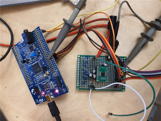
Stm is powered from USB and ADC analog and digital side is supplied with 5V using Keithley SMU.
Decoupling is made using 1uF electrolytic capacitors.
I’ve iterated through multiple adc with similar effects.
Problem is that it works only with oscilloscope connected.
But after reseting stm or connecting ground to logic analyzer or connecting digital pins to logic analyzer or after some time, it stops working.
I can make it work by:
Reseting adc with jumper,
disconnecting jumpers from logic analyzer,
Disconnecting ground from logic analyzer,
Reconnecting ground to logic analyzer,
and many other combinations.
Custom pcb adc schematic: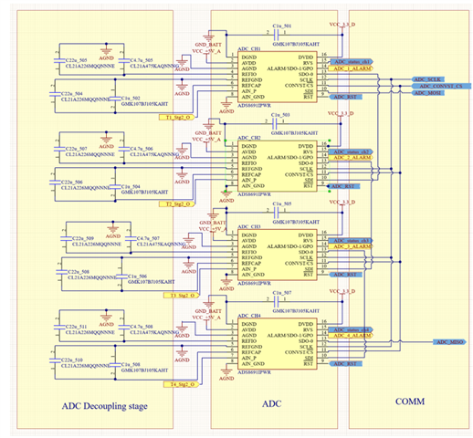
On custom PCB crosstalk, overshoot and undershoot due to parasitic were considerably lower.
Bypassing was made according to guidelines.
Note, there is a ground lead inductance that makes it look even worse.
(in all screens scope is triggering on SPI bus)
When it works data is clearly displayed 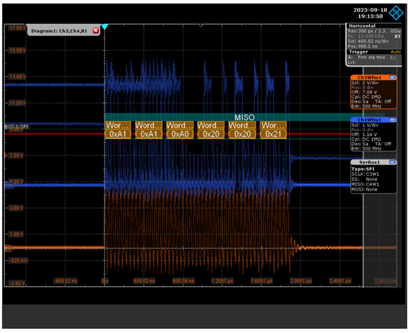
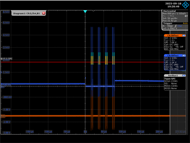
Sometimes after reseting, it looks like this: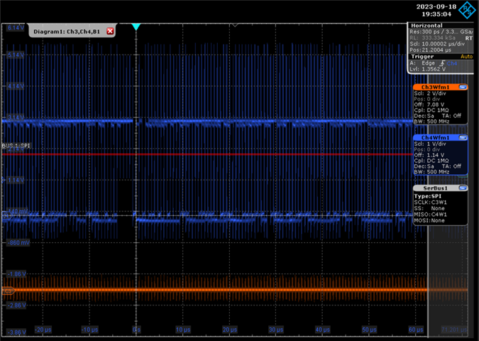
or it doesn’t work at all.
I’ ve tried also Pullups and pulldowns in mcu as well as in hardware close to ADC.
Different CLK speeds were also tested.
Code:
part from main:
void HAL_GPIO_EXTI_Callback(uint16_t GPIO_Pin)
{
	if(GPIO_Pin == ADC_ALARM_Pin)
	{
	   //This block will be triggered after pin activated.
		if(BUTTON_Pin == 1)
		{
			for(int i = 0; i < 4; i++)
			{
			read_hword_data();
	    	char *msg = "ADC Alarm working\r\n";
	        HAL_UART_Transmit(&huart2, msg, sizeof(msg), 100);
			}
		}
	}
}

void HAL_SPI_RxCpltCallback(SPI_HandleTypeDef * hspi)
{
    HAL_SPI_Receive_DMA(&hspi1, RX_Buffer, sizeof(RX_Buffer));
    if(sample < 50000)
    {
    	read_adc_data(&adc_handle, RX_Buffer, sample);
    	sample++;
    }
    else if(sample == 50000)
    {
    	char *msg = "50 000 samples gathered\r\n";
        HAL_UART_Transmit(&huart2, msg, sizeof(msg), 100);
    }

}
Custom library:
struct adc_state adc_init() {
	struct adc_state state;
/*
	for(uint16_t i=0; i<12500; i++) state.data0[i] = '\0';
	for(uint16_t i=0; i<12500; i++) state.data1[i] = '\0';
	for(uint16_t i=0; i<12500; i++) state.data2[i] = '\0';
	for(uint16_t i=0; i<12500; i++) state.data3[i] = '\0';
*/
	return state;
}

/*
 * 11000_xx_<9-bit address>_ <16-bit data>
 * Command used to clear any (or a group of) bits of a register.
 * Any bit marked 1 in the data field results in that particular bit of the specified register being reset to 0, leaving the other bits unchanged.
 * Half-word command (that is, the command functions on 16 bits at a time).
 * LSB of the 9-bit address is always ignored and considered as 0b.(2)
 */
void clear_hword(char *reg)
{
	char command[16];
	sprintf(command, "11000000%s", reg);
	HAL_SPI_Transmit(&hspi1, command, sizeof(command), 0);
}

/*
 * 11001_xx_<9-bit address>_ 00000000_00000000
 * Command used to perform a 16-bit read operation.
 * Half-word command (that is, the device outputs 16 bits of register data at a time).
 * LSB of the 9-bit address is always ignored and considered as 0b.
 * Upon receiving this command, the device sends out 16 bits of the register in the next frame.
 */
void read_hword(char *reg)
{
	char x[8] = "00000000";
	char command[16];
	sprintf(command, "11001000%s", reg);
	HAL_SPI_Transmit(&hspi1, command, sizeof(command), 0);
	HAL_SPI_Transmit(&hspi1, x, sizeof(x), 0);
}


void read_hword_data()
{
	if(HAL_GPIO_ReadPin(GPIOA, GPIO_PIN_3) == 1)
		{
			HAL_GPIO_WritePin(GPIOA, GPIO_PIN_4, GPIO_PIN_RESET);
			for(int i = 0; i < 4; i++)
			{
				read_hword(DATAOUT_CTL_REG);
			}
			HAL_GPIO_WritePin(GPIOA, GPIO_PIN_4, GPIO_PIN_SET);
		}
}

/*
 * 01001_xx_<9-bit address>_ 00000000_00000000
 * Same as the READ_HWORD except that only eight bits of the register (byte read) are returned in the next frame.
*/
void read_word(char *reg)
{
	char command[16];
	sprintf(command, "01001000%s", reg);
	HAL_SPI_Transmit(&hspi1, command, sizeof(command), 0);
}

/*
 * 11010_00_<9-bit address>_ <16-bit data>
 * Half-word write command (two bytes of input data are written into the specified address).
 * LSB of the 9-bit address is always ignored and considered as 0b.
 *
 * 11010_01_<9-bit address>_ <16-bit data>
 * Half-word write command.
 * LSB of the 9-bit address is always ignored and considered as 0b.
 * With this command, only the MS byte of the 16-bit data word is written at the specified register address. The LS byte is ignored.
 *
 * 11010_10_<9-bit address>_ <16-bit data>
 * Half-word write command.
 * LSB of the 9-bit address is always ignored and considered as 0b.
 * With this command, only the LS byte of the 16-bit data word is written at the specified register address. The MS byte is ignored.
 */
void write_word(char *reg)
{
	char command[16];
	sprintf(command, "11010000%s", reg);
	HAL_SPI_Transmit(&hspi1, command, sizeof(command), 0);
}

/*
 * 11011_xx_<9-bit address>_ <16-bit data>
 * Command used to set any (or a group of) bits of a register.
 * Any bit marked 1 in the data field results in that particular bit of the specified register being set to 1, leaving the other bits unchanged.
 * Half-word command (that is, the command functions on 16 bits at a time).
 * LSB of the 9-bit address is always ignored and considered as 0b.
 */
void set_hword(char *reg)
{
	char command[16];
	sprintf(command, "11011000%s", reg);
	HAL_SPI_Transmit(&hspi1, command, sizeof(command), 0);
}

/*
 * Configuration described in the documentation in chapter "7.6 Register Maps" (p.48)
 * https://www.ti.com/lit/ds/symlink/ads8691.pdf?HQS=dis-mous-null-mousermode-dsf-pf-null-wwe&ts=1660663610565&ref_url=https%253A%252F%252Fwww.mouser.co.uk%252F
 */
void id_config()
{
	if(HAL_GPIO_ReadPin(GPIOA, GPIO_PIN_3) == 1)
	{
		HAL_GPIO_WritePin(GPIOA, GPIO_PIN_4, GPIO_PIN_RESET);
		for(int i = 0; i < 4; i++)
		{
			write_word(DEVICE_ID_REG);
			char command[16];
			sprintf(command,"0000000000000000");
			HAL_SPI_Transmit(&hspi1, command, sizeof(command), 10);
		}
		HAL_GPIO_WritePin(GPIOA, GPIO_PIN_4, GPIO_PIN_SET);
	}
}

/*
 * Configuration described in the documentation in chapter "7.6 Register Maps" (p.48)
 * https://www.ti.com/lit/ds/symlink/ads8691.pdf?HQS=dis-mous-null-mousermode-dsf-pf-null-wwe&ts=1660663610565&ref_url=https%253A%252F%252Fwww.mouser.co.uk%252F
 */
void reset_config()
{
	if(HAL_GPIO_ReadPin(GPIOA, GPIO_PIN_3) == 1)
	{
		HAL_GPIO_WritePin(GPIOA, GPIO_PIN_4, GPIO_PIN_RESET);
		for(int i = 0; i < 4; i++)
		{
			write_word(RST_PWRCTL_REG);
			char command[16];
			sprintf(command,"0100010100100000");
			HAL_SPI_Transmit(&hspi1, command, sizeof(command), 10);
		}
		HAL_GPIO_WritePin(GPIOA, GPIO_PIN_4, GPIO_PIN_SET);
	}
}

/*
 * Configuration described in the documentation in chapter "7.6 Register Maps" (p.48)
 * https://www.ti.com/lit/ds/symlink/ads8691.pdf?HQS=dis-mous-null-mousermode-dsf-pf-null-wwe&ts=1660663610565&ref_url=https%253A%252F%252Fwww.mouser.co.uk%252F
 */
void sdi_config()
{
	if(HAL_GPIO_ReadPin(GPIOA, GPIO_PIN_3) == 1)
	{
		HAL_GPIO_WritePin(GPIOA, GPIO_PIN_4, GPIO_PIN_RESET);
		for(int i = 0; i < 4; i++)
		{
			write_word(SDI_CTL_REG);
			char command[16];
			sprintf(command,"0000000000000000");
			HAL_SPI_Transmit(&hspi1, command, sizeof(command), 10);
		}
		HAL_GPIO_WritePin(GPIOA, GPIO_PIN_4, GPIO_PIN_SET);
	}
}

/*
 * Configuration described in the documentation in chapter "7.6 Register Maps" (p.48)
 * https://www.ti.com/lit/ds/symlink/ads8691.pdf?HQS=dis-mous-null-mousermode-dsf-pf-null-wwe&ts=1660663610565&ref_url=https%253A%252F%252Fwww.mouser.co.uk%252F
 */
void sdo_config()
{
	if(HAL_GPIO_ReadPin(GPIOA, GPIO_PIN_3) == 1)
	{
		HAL_GPIO_WritePin(GPIOA, GPIO_PIN_4, GPIO_PIN_RESET);
		for(int i = 0; i < 4; i++)
		{
			write_word(SDO_CTL_REG);
			char command[16];
			sprintf(command,"0000000100000000");
			HAL_SPI_Transmit(&hspi1, command, sizeof(command), 10);
		}
		HAL_GPIO_WritePin(GPIOA, GPIO_PIN_4, GPIO_PIN_SET);
	}
}

/*
 * Configuration described in the documentation in chapter "7.6 Register Maps" (p.48)
 * https://www.ti.com/lit/ds/symlink/ads8691.pdf?HQS=dis-mous-null-mousermode-dsf-pf-null-wwe&ts=1660663610565&ref_url=https%253A%252F%252Fwww.mouser.co.uk%252F
 */
void data_config()
{
	if(HAL_GPIO_ReadPin(GPIOA, GPIO_PIN_3) == 1)
	{
		HAL_GPIO_WritePin(GPIOA, GPIO_PIN_4, GPIO_PIN_RESET);
		for(int i = 0; i < 4; i++)
		{
			write_word(DATAOUT_CTL_REG);
			char command[16];
			sprintf(command,"0100110000000000");
			HAL_SPI_Transmit(&hspi1, command, sizeof(command), 10);
		}
		HAL_GPIO_WritePin(GPIOA, GPIO_PIN_4, GPIO_PIN_SET);
	}
}

/*
 * Configuration described in the documentation in chapter "7.6 Register Maps" (p.48)
 * https://www.ti.com/lit/ds/symlink/ads8691.pdf?HQS=dis-mous-null-mousermode-dsf-pf-null-wwe&ts=1660663610565&ref_url=https%253A%252F%252Fwww.mouser.co.uk%252F
 */
void ref_vol_config()
{
	if(HAL_GPIO_ReadPin(GPIOA, GPIO_PIN_3) == 1)
	{
		HAL_GPIO_WritePin(GPIOA, GPIO_PIN_4, GPIO_PIN_RESET);
		for(int i = 0; i < 4; i++)
		{
			write_word(RANGE_SEL_REG);
			char command[16];
			sprintf(command,"0000000000000000");
			HAL_SPI_Transmit(&hspi1, command, sizeof(command), 10);
		}
		HAL_GPIO_WritePin(GPIOA, GPIO_PIN_4, GPIO_PIN_SET);
	}
}

/*
 * Configuration described in the documentation in chapter "7.6 Register Maps" (p.48)
 * https://www.ti.com/lit/ds/symlink/ads8691.pdf?HQS=dis-mous-null-mousermode-dsf-pf-null-wwe&ts=1660663610565&ref_url=https%253A%252F%252Fwww.mouser.co.uk%252F
 */
void alarms_config()
{
	if(HAL_GPIO_ReadPin(GPIOA, GPIO_PIN_3) == 1)
	{
		HAL_GPIO_WritePin(GPIOA, GPIO_PIN_4, GPIO_PIN_RESET);
		for(int i = 0; i < 4; i++)
		{
			write_word(ALARM_REG);
			char command[16];
			sprintf(command,"0000110000000000");
			HAL_SPI_Transmit(&hspi1, command, sizeof(command), 10);
		}
		HAL_GPIO_WritePin(GPIOA, GPIO_PIN_4, GPIO_PIN_SET);
	}
}

/*
 * Configuration described in the documentation in chapter "7.6 Register Maps" (p.48)
 * https://www.ti.com/lit/ds/symlink/ads8691.pdf?HQS=dis-mous-null-mousermode-dsf-pf-null-wwe&ts=1660663610565&ref_url=https%253A%252F%252Fwww.mouser.co.uk%252F
 */
void alarmh_config()
{
	if(HAL_GPIO_ReadPin(GPIOA, GPIO_PIN_3) == 1)
	{
		HAL_GPIO_WritePin(GPIOA, GPIO_PIN_4, GPIO_PIN_RESET);
		for(int i = 0; i < 4; i++)
		{
			write_word(ALARM_H_TH_REG);
			char command[16];
			sprintf(command,"0000000000000000");
			HAL_SPI_Transmit(&hspi1, command, sizeof(command), 10);
		}
		HAL_GPIO_WritePin(GPIOA, GPIO_PIN_4, GPIO_PIN_SET);
	}
}

/*
 * Configuration described in the documentation in chapter "7.6 Register Maps" (p.48)
 * https://www.ti.com/lit/ds/symlink/ads8691.pdf?HQS=dis-mous-null-mousermode-dsf-pf-null-wwe&ts=1660663610565&ref_url=https%253A%252F%252Fwww.mouser.co.uk%252F
 */
void alarml_config()
{
	if(HAL_GPIO_ReadPin(GPIOA, GPIO_PIN_3) == 1)
	{
		HAL_GPIO_WritePin(GPIOA, GPIO_PIN_4, GPIO_PIN_RESET);
		for(int i = 0; i < 4; i++)
		{
			write_word(ALARM_L_TH_REG);
			char command[16];
			sprintf(command,"0000000000000000");
			HAL_SPI_Transmit(&hspi1, command, sizeof(command), 10);		}
		HAL_GPIO_WritePin(GPIOA, GPIO_PIN_4, GPIO_PIN_SET);
	}
}

// Initialization of all ADC's registers
void adc_config()
{
	id_config();
	reset_config();
	sdi_config();
	sdo_config();
	data_config();
	ref_vol_config();
	alarms_config();
	alarmh_config();
	alarml_config();

}

//
void read_adc_data(struct adc_state *state, uint8_t *val, uint16_t x)
{
	x = x/4;
	receiver_check(state, val, x);
	read_hword_data();

}

//
void receiver_check(struct adc_state *state, uint8_t *val, uint16_t x)
{
	int16_t data;
	data = (val[3] << 8) | val[2];

