Other Parts Discussed in Thread: TMS320F28386S
Hello,I am using ADS7953 to get the voltage value outside,and processor is TMS320F28386S.
I wanna capture data from Channel 0 to 15, in Range 2 , so let the chip enter into Auto-2 mode .The sequence of commands as below:
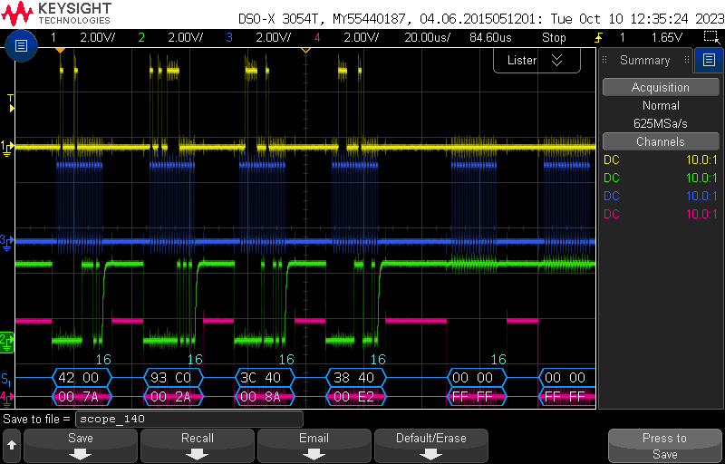
0x4200 -> 0x93C0 -> 0x3C40 -> 0x3840 -> 0x3840 -> 0x3840 -> ......
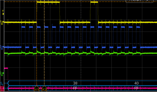
The results are resd from spi fifo as show in the picture below

result [0] may be the response of command 0x4200 ,
result [1]~[3] are the conversion results for CH0 ,and actually are correct .
but the rest are not correct.I am confused, please help me.
One further question, the design needs to sample all 16 channels at a pre-defined system frame rate (i.e. 1ms). The sequence above repeats every 1ms. Should I reset and reconfigure the device each frame by sending 0x4200 -> 0x93C0 -> 0x3C40 -> 0x3840 -> 0x3840 -> 0x3840 -> ......?
I really appreciate it if someone help me.
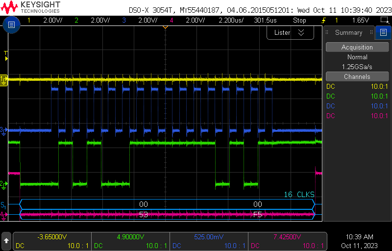
Y-SIMO, G-SOMI, B-CLK, R-CS
    SpiaTransmitData(0x4200);                 //frame(n-2),reset
    SpiaTransmitData(0x93C0);               //frame(n-1),program register
    SpiaTransmitData(0x3C40);             //frame(n),change to reset mode-2
    SpiaTransmitData(0x3840);           //frame(n+1),increment auto-2 mode
    for(i = 0;i < 16; i++)
    {
        SpiaTransmitData(0x3840);
        while(SpiaRegs.SPIFFRX.bit.RXFFST < 1){;}
        Chip1ChnData[i] = SpiaRegs.SPIRXBUF;
    }