Other Parts Discussed in Thread: AFE5808A, AFE58JD28, AFE5818
Hi, we are designing multiple AFE5828 on one board. some questions to consult.
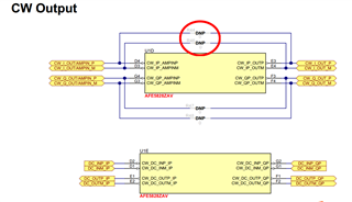
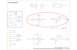
1. Ti's EVM board sch snapshot shown as below.
for pic 1, what's the purpose of resistor R44/R46 and R147(in pic2) , all 0 ohm, but DNP ?
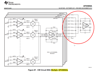
fo pic2, I think the multiple AFE's CW output (CW_IP/QP_OUTP/M), should be simply summed through RC, then output toJ52/54, and then conditioned and ADC sampled. So, is the U16/U17 (as red circle marked) just for EVM board testing?


2. We noticed ATGC input range(-0.4~+0.4V) is very different from AFE5808A (we used before, 0~1.5V). so we revise the signal conditioning circuits as below PIC, RANGING -0.5V~+0.5V. could you please help review ? thanks !
By the way, is the differential cap C2177 across the final TGC ouput (TGC_CtrlP/N nets) necessary?
Thanks very much !


