This thread has been locked.

If you have a related question, please click the "Ask a related question" button in the top right corner. The newly created question will be automatically linked to this question.

How long is the Integration Time at the DDC 101?

Other Parts Discussed in Thread: DDC112, DDC101

Hello,


I´m working with the DDC 101. I know this is a very old part, but the company wants still to work with it.But I´m new here and at the moment theres nobody here who can helb me.

I´ve read the DataSheet several times, but I do not really understand where I can see how I can calibrate the integration time. Is there a formula where I can see this. Or is the integration time always the same?

Thanks for your answers!


  • Today I already posted, that I have to work with the DDC 101?

    But perhaps I should work with an actual part. What DDC can replace the DDC 101?

    The DDC is connected to a photosensor and to a microcontroller named "Arduino". With this system I want to see at the pc what the photosensor is measuring.And also it should be possible to change the integration time with the PC.


    Thanks for your answers

  • Sven,

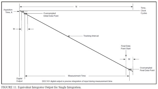
    The DDC101 is not recommended for new designs.  It would be preferable if you used the DDC112.  The initial question was in regards to changing the Tint time.  Tint is equal to the number of clock cycles used for the integration cycle divided by the frequency of the system clock (Tint = N/fclk.)  The number of clocks cycles used will include the acquisition time (K clocks), the initial and final data point number of samples (M) and the tracking interval.  Figure 11 of the datasheet shows this behaviour.  The tracking interval time is based on the point where the FDS (pin 8 of the DDC101) goes low.  This starts the final data point sampling. 

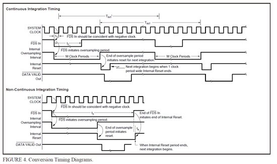
    So to control the integration time you can change the system clock frequency (0.5 to 2MHz), the acquistion time (K) and the number of times sampled (M) as specified by setting the parameters in the internal register, and the timing when the FDS pins goes low.  (See Figure 4.)

    Best regards,

    Bob B