This thread has been locked.

If you have a related question, please click the "Ask a related question" button in the top right corner. The newly created question will be automatically linked to this question.

ADC3664: SFDR vs Non-HD23

Part Number: ADC3664


Hello TI,

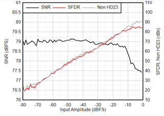
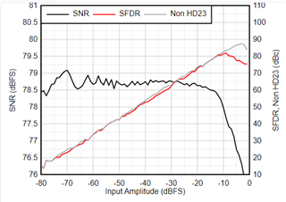
The top two Figures on sbas888b pg. 15 depict i.a. SFDR and Non-HD23. Since SFDR includes Non-HD23, Non-HD23 should always be equal to or better than SFDR. However, in the top two figures, these two plots cross each other and furthermore, Non-HD23 is normally weaker than SFDR, which is interesting, to say the least.

Would it be possible to have those figures checked and corrected, please?

By the way, that phenomenon, that the Non-HD23 or SPDR is nearly constant (in dBFS) over input amplitude (in this case more or less -95 dBFS), therefore implying that SFDR cannot meaningfully be improved by filtering the input - does TI have any write-up on this?

  • Hello TI, would it be possible to confirm that the figures in question are indeed incorrect?

  • Hi Bernhard,

    I am not clear on why you are thinking that these two figures are incorrect? Figure 6-15/6-16 is what I am assuming you are referring to.

    Please confirm.

    Also, filtering the analog input would improve SFDR, this the HD2/3 are typically very strong would usually define the SFDR measurement.

    Regards,

    Rob

  • Hello Rob,

    1) Yes, correct, sbas888b Figures 6-15 and 6-16 is what was referred to. Since:

    SFDR = worst(HD2, HD3, HD4, HD5, HD6, HD7, ...)

    and: Non-HD23 = worst(HD4, HD5, HD6, HD7, ...)

    Thus Non-HD23 should always equal to or better than SFDR. Do you agree? If so, Figures 6-15 and 6-16 cannot be correct. As a counterexample, sbas887 Figures 6-12 and 6-13 are in line with expectations (Non-HD23 always better than or equal to SFDR).

    2) Regarding the effect of filtering or not: As an example, let's work with the Non-HD23 in sbas887 Fig. 6-12. Suppose an unwanted input of -5 dBFS present somewhere on the input of the ADC results in a spur of -90 dBc (grey line) = -95 dBFS near a wanted signal.

    Suppressing this -5 dBFS unwanted by 10 dB in an external filter could result in a spur amplitude of -15 dBFS - 80 dBc = still -95 dBFS, i.e. no change in the spur amplitude near the wanted.

    Suppressing this -5 dBFS unwanted by 10 dB still could result in a spur amplitude of -15 dBFS - 80 dBc = -95 dBFS, i.e. no change in the spur amplitude near the wanted.

    Expending more effort and suppressing that -5 dBFS unwanted by say 65 dB in an external filter still 'only' achieves a possible spur amplitude of -70 dBFS - 30 dBc = -100 dBFS.

    Thus 65 dB external filtering improves the Spur Floor by only 5 dB which cannot be improved by decimation (since the spur is near the wanted). Thus external filtering can only improve the spurious response by a very limited amount close to a wanted signal. Do you concur?

  • Hi Bernhard,

    1) I will check with design to see if the datasheet figures are incorrect. I suspect they are correct, as the non-HD2/3 is very close in all the other figures and even tho they seem to be better than HD2/3, it still could be a limitation to the design of the device. Give me a few days to get back with you on this to confirm.

    2) I agree, with your second example. Another way to try to improve this is use a very narrow filter, however, that adds more loss on the frontend. So its a delicate balance/tradeoff in how much more spurious attenuation might be improved here.

    Regards,

    Rob

  • Hi Bernhard,

    I spoke to design, the two figures are correct.

    The non-HD2/3 is performance is part of the design as I suspected.

    Regards,

    Rob

  • Hello Rob,

    Would it be possible to confirm this understanding:

    SFDR = worst(HD2, HD3, HD4, HD5, HD6, HD7, ...)

    and: Non-HD23 = worst(HD4, HD5, HD6, HD7, ...)

    Is this correct?

  • Hi Bernhard,

    Yes, this is correct.

    Regards,

    Rob

  • Hello Rob,

    Thank you for the confirmation of those definitions. It then follows as a consequence that SFDR can never be better than Non-HD23 (SFDR includes all worst Non-HD23 and additionally the HD23 which will sometimes be worse than HD4>).

    Therefore, sbas888b Figures 6-15 and 6-16 cannot be correct since, for instance Figure 6-16 has SFDR better than Non-HD23 for most of the graph. This a non sequitur given the definitions. Also, SFDR and Non-HD23 can never cross, as in Figure 6-15. They can touch, but never cross each other.

    Would it be possible to have those two Figures rechecked, please? Perhaps you could appeal to a higher authority in design. Else, please give an example explicitly listing hypothetical values of HD2, HD3, HD4, HD5, HD6, HD7, ... which could show how SFDR could be better than Non-HD23.

  • Hello Rob,

    Has design perhaps responded?

  • Hi Bernhard,

    Sorry for the late response, I am waiting to hear back from design. 

    I wonder in this case SFDR only reports HD2 or HD3, whichever was worst, which I believe is your point.

    I will update you tomorrow on what I find out.

    Regards,

    Rob

  • Hello Rob,

    Any update?

  • Hi Bernhard,

    I just wanted to chime in a bit here while others on the team are out for holiday.

    Else, please give an example explicitly listing hypothetical values of HD2, HD3, HD4, HD5, HD6, HD7, ... which could show how SFDR could be better than Non-HD23.

    A case like above can show when the device is operating in decimation mode with frequency planning such that HD2,HD3 fall out of band and SFDR is limited by one of the higher order harmonics. I don't have any exact example to provide to you with numbers but this occurs frequently in ADCs offering on-chip decimation at some frequencies which were not frequency planned correctly. Ideally, you can utilize decimation to filter out these higher order spurs by the attenuation spec of the decimation filter, often 85dB.

    Regards, Chase

  • Hi Bernhard, 

    I am still working with the design team. I will inform them to help make a quicker response.

    I apologize for the delay.

    Thanks,

    Rob

  • Hello Chase,

    If these definitions are correct:

    SFDR = worst(HD2, HD3, HD4, HD5, HD6, HD7, ...)

    and: Non-HD23 = worst(HD4, HD5, HD6, HD7, ...)

    Then it cannot be that SFDR is ever better than Non-HD23. At best Non-HD23 can be equal to SFDR (let's take your example where HD2 and HD3 fall out of band completely and play absolutely no role in the response). Any remaining harmonics present in the SFDR will also be present in Non-HD23.

    By definition, Non-HD23 takes SFDR and removes the effect of HD2 and HD3. This means that Non-HD23 can only improve relative to SFDR or be equal, never worse.

  • Hi Bernhard, 

    Yes, your understanding aligns. This is precisely what I said when "HD2,HD3 fall out of band and SFDR is limited by one of the higher order harmonics" in my post above. This understanding is correct. I agree with you that these datasheet plots are not making sense because SFDR should always be less than or equal to the Non-HD2,3 spec. My only guess for this discrepancy is the datasheet plot traces were taken at different sweeps rather than using the same data for the SFDR and then ignoring HD2,3 to calculate the Non-HD2,3 trace. I'd be willing to bet that is what is going on here and the differences are due to traditional capture variance. We could set this up in the lab and retake this data with averaging, but this would have to wait until the middle of next week or so.

    Regards, Chase

  • Hi Bernhard,

    I have confirmation that the datasheet plots are incorrect and the datasheet will be updated.

    I am not awaiting confirmation what data I can post.

    Regards,

    Rob

  • Hi Bernhard,

    I want to thank you for bringing this to our attention.

    Here is the new data that will be updated in the datasheet early next year.

    Regards,

    Rob

    5MHz AIN

    70MHz AIN

  • Hello Rob,

    Thank you, these look much better. Regarding my second question:

    Noting that the Non-HD23 or SFDR is nearly constant (in dBFS) over input amplitude (in this case more or less -95 dBFS), therefore implying that in-band SFDR (falling onto or close to the wanted) cannot meaningfully be improved by filtering the input (to suppress the unwanted which was causing the spurs even if this unwanted was out of band and even with quite a steep filter):

    Does TI have any official write-up on this? What phenomenon in the ADC causes the spur amplitude to remain nearly unchanged, even if the level of the spurious-causing input is substantially reduced?

  • Hi Bernhard,

    This can be driven mostly by the internal ADC architecture and inner-stage gain errors.

    If you asking can the non-HD23 be improved, regardless of input level, then you may need to add an external dithering circuit and sum the noise dithering at the input of the ADC with the signal being sampled.

    Some ADCs have a dithering feature internally, some do not.

    If this what you are referring to, I can send you a few links to some papers.

    Regards,

    Rob

  • Hello Rob,

    Thank you. Does TI have an intuitive explanation why spurs due to an input signal would not reduce when the input signal causing the spurs reduces in amplitude substantially?

  • Hello Rob,

    Does TI have any write-up on this which you may be aware of?

  • Hi Bernhard,

    Sorry for the delay. See the links below to help describe this.

    https://www.analog.com/media/en/training-seminars/tutorials/MT-024.pdf

    https://www.analog.com/media/en/training-seminars/design-handbooks/Data-Conversion-Handbook/Chapter5.pdf

    If the non-HD23 spurious are of concern. You can try using external dither in order to help push these further into the noise floor.

    www.analog.com/.../319765654an-410.pdf

    Thx,

    Rob