This thread has been locked.

If you have a related question, please click the "Ask a related question" button in the top right corner. The newly created question will be automatically linked to this question.

ADS114S08: How to remove noise when Multiple 4 Wire RTD measurement in parellel ?

Part Number: ADS114S08

Hello TI Team,

We make circuit using ADS114S08 to measure temperature.

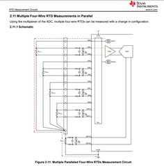
In our system we connect 4 number of 4 wire RTD in parallel as per application note : " A basic guide to RTD measurements ".

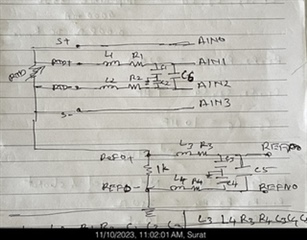
When we measure temperature, noise is present.

So how to calculate RC low pass filter value and corner frequency for these multiple RTD ?

So that we can remove noise from each other and no affect on other channel when we measure one channel.

  • Hi Manoj H,

    One input channel should not be affecting the others unless you are not waiting for the changes in analog settling to complete.  What is often seen with these types of measurements is decay from one input channel affecting the charge cycle of another channel measurement. It would be helpful to know what the filter values are that you are currently using.  It would also be helpful to know the precise ADC register configuration and RTD reference resistor you are using.

    First we should try to determine precisely what you are seeing.  Here is what I would recommend and that is only connecting one RTD and measuring it.  If you look at a single channel while not switching the mux, do you see good results?  If you do not, then most likely you are picking up EMI/RFI on your wiring.  This will require some effort to reduce the affect of the noise which may include the addition of some ferrites in series with the RC filters.  You could also change the values of the RC filters, but when doing so the settling time will increase.  The fc for the filter will depend on both the required settling response and the speed of the acquisition.  At this point I know neither how fast you want to cycle the mux nor the data output rate you intend to use.

    If you see that one RTD looks good, then you would add a second to see the response between the two.  Here you may see the affects of analog settling which may require some delay following  a channel change.  You can use the predefined delays to automatically set additional delay when changing channels.  The setting is the DELAY bits in the PGA register (0x03).

    Best regards,

    Bob B 

  • Hi Bob B,

    Thank you for your valuable reply.

    As per your suggestions, we will check and give feedback.

  • Hi Bob B,

    We have configured ADS114S08 as follows :

    * 4 RTDs connected in 4 wire configuring with lower side reference.
    * 1Kohm Reference resistor used.
    * Data rate 100 SPS.
    * D-chop enabled.
    * Sinc3 filter.
    * 14t delay.
    * 2000 mA excitation current.
    * All four RTDs connected with 10 meters wire length to the input using twisted pair cables & shield.
    * Gain of 4.

    We tried sampling one channel among the four to avoid switching delay.

    To our observation it was found that the reading of sensor is stable as soon we start motor connected through inverter, the reading shift 2 to 4 degree & remain stable. When Motor stopped, we get original value of RTD.

    As you said, we connect ferrite bead in series with each input channel before RC Low pass filter. Channel switching delay went high and sensor value shift with 3 degree, but the variation due to motor become less.

    Kindly please suggest.

  • Hi Manoj H,

    Welcome to real world system design. I can give some additional information  but I'm currently out of office so it will have to wait until next Tuesday.

    Best regards,

    Bob B

  • Hi Manoj H,

    It is difficult to tell how you are prototyping your system.  Often times there are poor grounds and wiring loops that can pick up extraneous signals.  As far as additional components, you may benefit from having TVS diodes for steering large transients to ground away from the ADC inputs.  Using shielded cables that are properly terminated to ground can also be a benefit.

    There are a number of TI Precision Labs videos that may be beneficial for you to review.

    https://www.ti.com/video/series/precision-labs/ti-precision-labs-analog-to-digital-converters-adcs.html

    Look in particular at the topic sections:

    • Electrical overstress on data converters
    • PCB design for good EMC

    Hopefully these videos can help you decide the steps you need to take to achieve the desired level of performance.

    Best regards,

    Bob B

  • Hello Bob B,

    Thank you for your reply.

    Due to out of office, i reply late to you.

    We connect 100nF ceramic capacitor between junction point at which all RTD's wire meet & analog GND.

    We achieve the desired level of performance.