This thread has been locked.

If you have a related question, please click the "Ask a related question" button in the top right corner. The newly created question will be automatically linked to this question.

ADS1285: ADS1285 power supply

Part Number: ADS1285
Other Parts Discussed in Thread: REF6241, REF6250, DAC1282

Hi team,

I do not find the typical application when AVSS is -2.5V in the data manual. I wanna know the values of AVDD1, AVDD2, IOVDD and other parameters when AVSS is -2.5V. I would be appreciated if you can give me an Application

  • Hello,

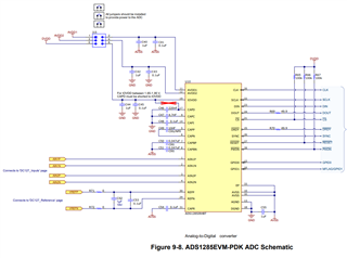
    Please look at the ADS1285EVM-PDK users guide.  The schematics show how to configure the ADC for +/-2.5V power supplies with respect to AGND.

    With AVSS=-2.5V:

    AVDD1=AVDD2=+2.5V

    DGND=AGND

    IOVDD=+2.7V to +3.6V.

    The reference circuit should also be referred to the AVSS supply (REFN=AVSS=-2.5V), which will still allow use of a 2.5V, 4.096V, or 5V reference.

    All digital inputs, including the CLK, are referred to DGND=AGND.

    Regards,
    Keith Nicholas
    Precision ADC Applications

  • Thanks for solving my confusion.

    I conducted Tina simulation of REF62xx in the power supply environment you provided , and found that REFP=REFN=-2.5V, is this the right situation?

    and you mentioned "which will still allow use of a 2.5V, 4.096V, or 5V reference."Does that mean I can provide ads1285 with REFP=2.5V REFN=-2.5V while AVSS=-2.5V?

  • Hello,

    If I recall, the TINA REF62xx model does not work correctly if the ground pins of the model are not connected to the simulation ground, so unfortunately, you cannot simulate using this voltage configuration.  However, the actual part will work in this configuration.

    Yes, you can set REFP=2.5V and REFN=-2.5V when AVSS=-2.5V.  As an example using the REF6241, connect the VIN pin to AVDD=+2.5V and the ground pins to AVSS=-2.5V.  The output will still be 4.096V relative to AVSS.

    Regards,
    Keith

  • Hi, team.

    With AVSS=-2.5V , AVDD1=AVDD2=+2.5V , DGND=AGND , IOVDD=+2.7V to +3.6V. The voltage I tested was: REFP=0V and REFN=-2.5V. In this situation, Do I need to select 2.5V reference to config the registers? and if I wanna select 4.096V, or 5V reference you mentioned above, AVDD1's votage should be higher than 4.096V or 5V , which is referred to AVSS, but not higher than 5.5V mentioned in ads1285 user manual.Is it right?

  • Hi xingwitt,

    This is a holiday week in the US, therefore we will get back to you next week with a response. Thank you for your patience

    -Bryan

  • Hello Xingwitt,

    Do I need to select 2.5V reference to config the registers?  Yes, in this case the reference voltage is +2.5V, and the CONFIG1 register should be set to REF[1:0]=10b.

    If you want to use 4.096V for Vref, then AVDD1=2.5V and AVSS=-2.5V in this case.  The ground pins of the REF6241 are connected to AVSS in this case.  REFN (referred to GND) will be -2.5V, and REFP (referred to GND) will be 1.596V.  The differential reference voltage will be 4.096V [1.596 - (-2.5)].

    If you want to use 5.0V for Vref, then AVDD1=2.8V and AVSS=-2.5V in this case.  Similar to the 4.096V case, the REF6250 ground pins are connected to AVSS.  REFN (referred to GND) will be -2.5V and REFP (referred to GND) will be +2.5V, with a total differential voltage (REFP-REFN) =+5V.

    Regards,
    Keith

  • Hi team,

    "If you want to use 4.096V for Vref, then AVDD1=2.5V and AVSS=-2.5V in this case.The ground pins of the REF6241 are connected to AVSS in this case.  REFN (referred to GND) will be -2.5V, and REFP (referred to GND) will be 1.596V."

    Here is the peoblem: In ADS1285-EVM , I modified the output AVDD1 and  AVDD2 using R10/R12/R13,R16/R18/R19 to the ground ,thus I can get AVDD1 = AVDD2=2.5V(which were referred to GND) . And I connected AVSS to BIPOL in J4 , gave a negative input,also,all jumpers were installed in J15. But when I tested the voltage of AVDD1,it turned out to be 0V, AVDD2 was still 2.5V,and ref6241's REFP=0V. If I want to use 4.096V for Vref,then AVDD1 should be 5V(referred to GND) ,right?

  • Hello Xingwitt,

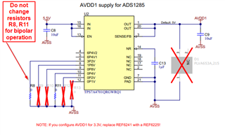
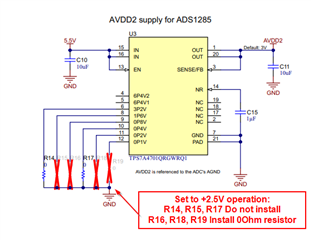
    If you are using the ADS1285EVM, in order to configure it for bipolar operation, you only need to change the level on AVDD2 to +2.5V.  AVDD1 should not be changed, and its voltage level should be kept at 5V relative to AVSS.  When setting AVSS to -2.5V (setting jumper J4 to BIPOL and providing a negative supply voltage of at least -3V to J3), AVDD1 will now measure +2.5V relative to GND.

    Do not change voltage settings for AVDD1:

    Change resistor settings for AVDD2 for 2.5V operation:

    Regards,
    Keith

  • Hi ,team!

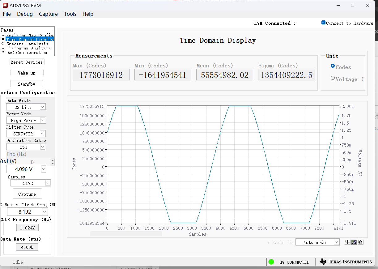
    I ran some testswith ads1285-evm. I gave it a sinusoidal signal of -+ 2.5V,the captured signal is shown below

    Is the max/min test voltage -+2.5V?why voltages above 2V can't be caught, Is there a problem with the register configuration?

  • Hi xingwitt,

    Keith is out for the holidays here in the US, please expect a response sometime during the week of Jan 1

    Thanks for your patience

    -Bryan

  • Hello Xingwitt,

    I assume you are using an external function generator, since the maximum output voltage of the DAC1282 is +/-2.048V when using the 4.096V reference included with the EVM.

    I am guessing that you have a single-ended connection to the EVM from your function generator.

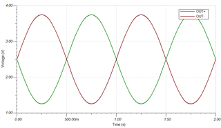
    The external function generator needs to be a differential output, with a common mode voltage set very close to +2.5V.  Each of the outputs of the function generator (OUT+ and OUT-) will then range from 1.25V to 3.75V with 180deg phase shift between the two outputs.

    Regards,
    Keith