Because of the holidays, TI E2E™ design support forum responses will be delayed from Dec. 25 through Jan. 2. Thank you for your patience.

This thread has been locked.

If you have a related question, please click the "Ask a related question" button in the top right corner. The newly created question will be automatically linked to this question.

ADS124S08: Data read/write from ADS124S08 to MSPM0G3507.

Part Number: ADS124S08
Other Parts Discussed in Thread: MSPM0G3507, , LP-MSPM0G3507, SYSCONFIG,

Hello TI,

I am interfacing 3 wire RTD PT1000 sensor with ADS124S08 and MSPM0G3507. 

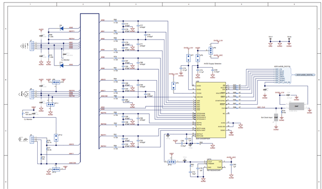
Reference circuit/Schematic is ADS124S08 datasheet example page no. 91. 

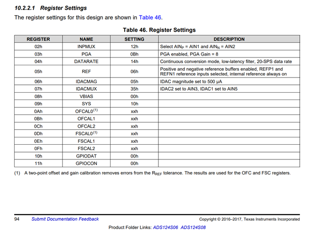
Below are the register setting.
int main (void)
 {
    delay_cycles(80000); //2.2ms delay  as per data sheet of ads124s08
    
    SYSCFG_DL_init();
  
    DL_GPIO_clearPins(GPIO_SPI_0_CS0_PORT,GPIO_SPI_0_CS0_PIN);  //cs low

    delay_cycles(16000); 

    DL_SPI_transmitData8(SPI_0_INST,RESET_OPCODE_MASK);  //reset device

    delay_cycles(128000);

    regWrite(REF_ADDR_MASK,0x06);         


    regWrite(PGA_ADDR_MASK,0x0A);          //0A// PGA enabled, Gain = 4

    regWrite(INPMUX_ADDR_MASK,0x12);       //12// Select AINP = AIN1 and AINN = AIN2

    regWrite(IDACMAG_ADDR_MASK,0x07);      //07// IDAC magnitude set to 1mA


    regWrite(DATARATE_ADDR_MASK,0x14);

    regWrite(SYS_ADDR_MASK,0x10);


    regWrite(IDACMUX_ADDR_MASK,0x35);      //35;// IDAC1 set to AIN5, IDAC2 set to AIN3

   
    readRegs(INPMUX_ADDR_MASK,5,Data);     //trying to read 5 register starting from register address 0x02 

    DL_SPI_transmitData8(SPI_0_INST,START_OPCODE_MASK);     //start command

    delay_cycles(16000);

    DL_GPIO_setPins(GPIO_SPI_0_CS0_PORT,GPIO_SPI_0_CS0_PIN);  //cs high

    while (1)
    {
        if (!DL_GPIO_readPins(GPIO_LEDS_DRDY_ADC_PORT, GPIO_LEDS_DRDY_ADC_PIN))  //waiting  for DRDY pin to goes low
        {
            DL_GPIO_clearPins(GPIO_SPI_0_CS0_PORT,GPIO_SPI_0_CS0_PIN);  //cs low
            delay_cycles(16000);

            DL_GPIO_setPins(GPIO_LEDS_START_PORT,GPIO_LEDS_START_PIN); //testing
            delay_cycles(16000);

            DL_SPI_transmitData8(SPI_0_INST,RDATA_OPCODE_MASK);


            #if 1
                        for(int i=0;i<3;i++)
                        {
                            Input_Data[i] = DL_SPI_receiveData8(SPI_0_INST);
                        }
            #endif
                        delay_cycles(16000);
                        DL_GPIO_setPins(GPIO_SPI_0_CS0_PORT,GPIO_SPI_0_CS0_PIN);
            }
     }
}}
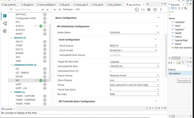
SPI setting

  • SPI Mode 1
  • clock bit rate 1MHz
  • Bit order - MSB first

We followed datasheet pseudo code but not getting data from ADC. When reading SPI RX buffer some random value comes.

We are not sure ADC get configured or not. 

IDAC magnitude not set as per setting 500uA.

  • Hi Omkar Singh,

    Can you provide the complete schematic and oscilloscope or logic analyzer shots of the communication?

    Thanks,

    Bob B

  • Hi Bob,

    I am using ADS124S08 EVM, I have removed JP9, JP5, JP7, JP6.  AVDD is excited by 5V and IOVDD, DVDD excited by 3.3V using LP-MSPM0G3507 EVM.

    SPI is connected with LP-MSPM0G3507 SPI. RTD is connected with J7(1,2,4).

  • Hi Omkar Singh,

    I would recommend adding a jumper to location JP1 of the EVM (this holds the onboard micro into a reset state and disables the level shifters) and connecting the USB to power the EVM.  Make sure that all of the power jumpers you removed are replaced.  Instead of using the power from the LP, just connect the ground of the LP to the EVM.  This will greatly reduce the wiring between the LP and the EVM.

    If you are still having communication issues, send oscilloscope or logic analyzer shots of the communication for verification.

    Best regards,

    Bob B

  • Hi Bob,

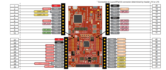
    For the ADS124S08, I have shorted JP1, and SPI pin connected to MSPM0G3507 EVM as below.


    ADS124S08 EVM

    MSPM0G3507 EVM

    SDO

    PB8

    SDI

    PB7

    CS

    GND

    SCLK

    PB9

    DRDY

    A12

    START

    PB16

    RESET

    PB17

    GND

    GND


    Registers are configured as below.


            regWrite(STATUS_ADDR_MASK,0x80);

            regWrite(INPMUX_ADDR_MASK,0x12);       //12// Select AINP = AIN1 and AINN = AIN2

            regWrite(PGA_ADDR_MASK,0x09);          //0A// PGA enabled, Gain = 2

            regWrite(DATARATE_ADDR_MASK,0x14);

            regWrite(IDACMAG_ADDR_MASK,0x07);      //07// IDAC magnitude set to 1mA

            regWrite(IDACMUX_ADDR_MASK,0x35);      //35;// IDAC1 set to AIN5, IDAC2 set to AIN3

            regWrite(VBIAS_ADDR_MASK,0x00);

            regWrite(SYS_ADDR_MASK,0x10);

            regWrite(REF_ADDR_MASK,0x16);

            regWrite(OFCAL0_ADDR_MASK,0x00);

            regWrite(OFCAL1_ADDR_MASK,0x00);

            regWrite(OFCAL2_ADDR_MASK,0x00);

            regWrite(FSCAL0_ADDR_MASK,0x00);

            regWrite(FSCAL1_ADDR_MASK,0x00);

            regWrite(FSCAL2_ADDR_MASK,0x40);

            regWrite(GPIODAT_ADDR_MASK,0x00);

            regWrite(GPIOCON_ADDR_MASK,0x00);


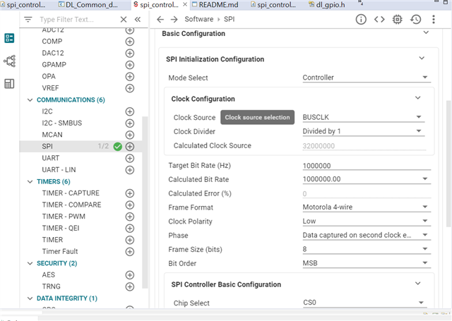
    SPI clock setting


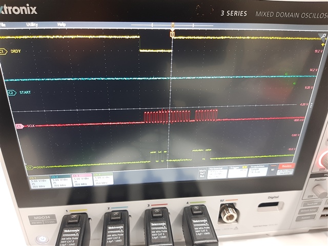
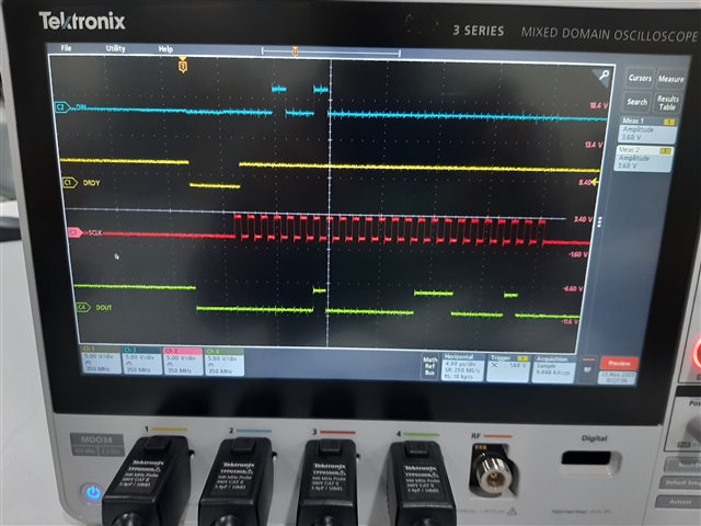
    Oscilloscope wave form


    RTD connection


    PT1000 , 3- wire,

    ADS124S08 EVM (J7)

    RTD

    A1

    RTD wire first

    A2

    RTD wire second(common)

    A0

    RTD wire three(Common)


    Problem

    1. IDAC not set 1mA as per setting. Voltage across RTD A1 and A2 is 28mV.
    2. Data value is Garbage.

     Kindly, help on this.

  • Hi Omkar Singh,

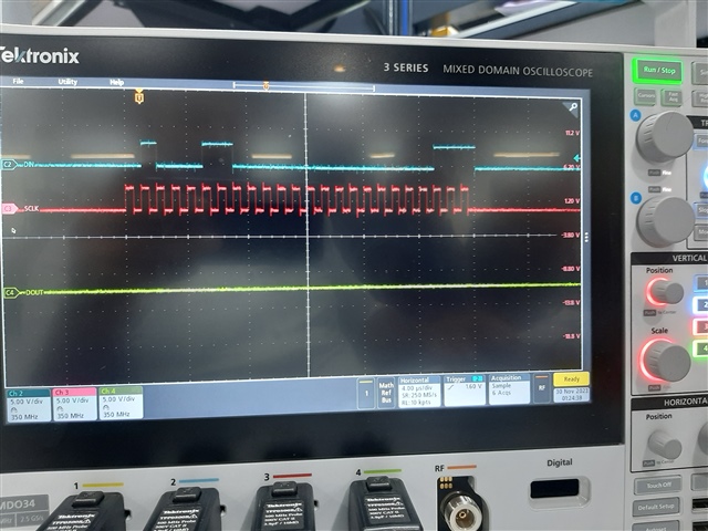
    As DRDY is pulsing, it does appear that the ADS124S08 is functioning.  I think you are just trying to do too much all at once.  Verify that your communication is working first before doing anything else.  It would appear that you have the connections reversed for SDI and SDO.  SDI should connect to PICO which is PB8 and SDO should connected to POCI which is PB7.

    Before trying to write anything to the device I would suggest reading the registers to verify you are getting the default values.  I am a little confused in that you use 4-wire SPI mode in Sysconfig, but you show that CS at GND.  I guess this should be ok, but it is just not clear.  However it would be beneficial to see the communication in detail.  Using the RREG command you should see what the default values are in your result.  Both the scope shots and the code returned values should agree.  If they do you can proceed to writing the registers and you should verify that what you thought you wrote to the device agrees with another register read of the same registers.

    Lastly, I see a lot of SCLK transitions between DRDY pulses.  It is not clear what you are attempting to do here.  Can you clarify what you are trying to write on the SPI bus between the DRDY pulses?

    Best regards,

    Bob B

  • As Per suggestion instade of doing so many thing at once we first read back default registers value successfully then we set some resisters as per datasheet and again readback those registers to check whether they set correctly or not and we get same resister(updated) value on readback. It means adc is correctly responding means communication looks good. Now please see image I have attached and let me know what is wrong with my data read . instead of starting at raising edge of DRDY pulse it started at falling edge of DRDY pulse.Excelworksheet.xlsx

  • Hi Mehul Dabholkar,

    If I understand correctly you are using reading direct mode (no RDATA command).  When DRDY transitions from high to low new conversion data are available to be read from the output buffer.  So the response appears to be correct.  Where the issue lies is DRDY is not transitioning high in response to the first first falling edge of SCLK.  When reading data direct the response should look like Figure 90 in the datasheet.

    In your scope shot it appears that the ADS124S08 is not seeing the first byte of SCLKs but instead is responding to the second byte.  I cannot explain what is going on as I do not know if you have anything else connected to the SPI bus or if you are now using CS. 

    Best regards,

    Bob B 

  • Hi Bob

    please see below code

    START MAIN--

    delay_cycles(160000); //wait for POST operation

    SYSCFG_DL_init(); // init all gpio and spi with spi mode 1

    delay_cycles(32000); //required min 20ns we provide 1ms delay

    DL_SPI_transmitData8(SPI_0_INST,RESET_OPCODE_MASK); // optional to send reset command to make sure device is properly reset

    delay_cycles(160000); // delay of min of 4096*tclk

    readRegs( ID_ADDR_MASK,19,Data); // reading default register

    ADS124S08_Init(); // writing register as per datasheet

    readRegs_after( ID_ADDR_MASK,19,Data); //reading back register to verify

    DL_SPI_transmitData8(SPI_0_INST,WAKE_OPCODE_MASK); //to make sure device is wakeup

    DL_GPIO_setPins(GPIO_LEDS_START_PORT,GPIO_LEDS_START_PIN); // pulling start pin to high keeping device in contineous conversion mode
    delay_cycles(2240000);

    DL_SPI_transmitData8(SPI_0_INST,SFOCAL_OPCODE_MASK); // self calibration
    delay_cycles(32000);

    while(1)
    {
    if (!DL_GPIO_readPins(GPIO_LEDS_DRDY_ADC_PORT, GPIO_LEDS_DRDY_ADC_PIN)) // check of low transition of DRDY pin
    {

    DL_SPI_transmitData8(SPI_0_INST,RDATA_OPCODE_MASK); //sending data read command

    data = dataRead(&dStatus, &dData, &dCRC); // reading data
    }
    }

    END MAIN--

    So you can see that we are sending RDATA command . and we are not using CS pin now . We made CS pin LOW by connecting it to ground permanently.  do i need to introduce some delay before sending RDATA command? 

  • Hi Bob 

    i also want to ask you instead of interrupt based DRDY pin. is it ok to do it by polling? does this make any difference?

  • Hi Mehul Dabholkar,

    You do not need to use interrupt method, but usually that method is more reliable in an overall programming loop.  We have seen many customers that use the polling method.

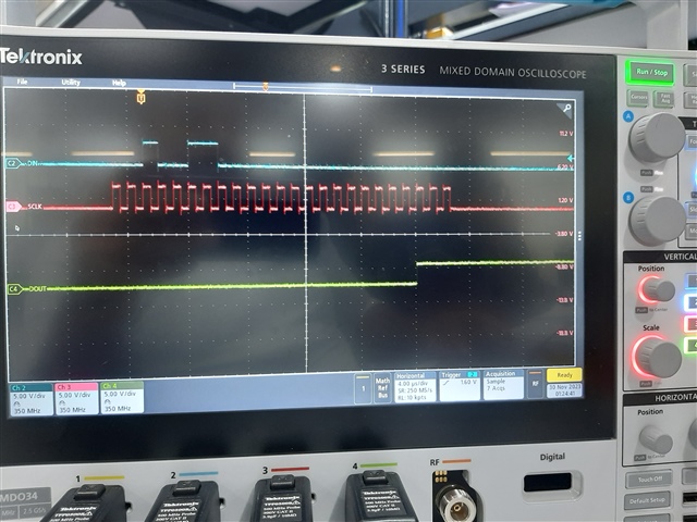
    From the code above it looks as though you are polling the DRDY pin.  However in your scope shot previously all I saw was 24 SCLKs for data and did not see SCLKs for the RDATA command.  Usually the RDATA command would be a part of the dataread function.  This should be similar to the read and write register functions, but that should not make any significant difference.

    You do not require any delay between the DRDY going low and the reading of conversion data.  It should be available as soon as DRDY transitions low.  Instead of monitoring the START pin it may be more advantageous to view the DIN pin to verify the proper command and communication is being sent.  It is still not clear why DRDY does not go back high with the first falling edge of SCLK.

    Best regards,

    Bob B

  • Hi Bob,

    Thank you.

    Below is the connection.

    ADS124S08 EVM

    RTD

    J7 – A1

    1

    J7- A2

    2(Common resistance)

    J7- A0

    3 (Common resistance)

    The output count is 5 digit long 65279. As IDAC is set on 1mA but voltage across RTD and reference resistor R68(1k) is 0.03 V. why is it so?

    When we set IDACMAG register it automatically reset all the resistors.

  • Hi Omkar Singh,

    I really think that you are attempting to do too much with your code all at once instead of taking it step by step. First before doing anything else read the registers to make sure that you are reading back the default values of the registers after power up.  Second step is to write just one register with a value different from the default value and then read it back with a single register read.  Third, write the desired configuration and read it back with a register read.  Fourth, read the voltages across the reference resistor and RTD to verify that the configuration and wiring are working as intended.  Fifth is to read back the conversion data from the ADC.  If you are having any issues along the way, then provide the scope or logic analyzer shots of the communication for me to review.

    If by writing contents to the register the device resets, then you are having a wiring issue or are inadvertently sending the RESET command or pulsing the RESET pin.  Make sure that the RESET pin is not floating and is solidly pulled high.

    Best regards,

    Bob B

  • Hi Bob

    We are able to read default registers and we are getting exact same values as mentioned in datasheet. after that i am writing required resisters and also read back the same. till this step we are not getting any issue. but even if I am setting IDACMAG to 1mAmp. i am not getting desired voltage at J7 connector or R68 resister. i am attaching the scope image. also, I am following Pseudo code as mentioned in data sheet only with change of I am using 3 wire SPI (CS tie to low) but in am not getting waveform as mentioned in datasheet.  you can see that i an sending REDATA command 0x12.  

    following coding sequence I m following as mention in datasheet.

    1. System init
    2. Sent RESET Command
    3. Read Default resisters
    4. Writing config registers (one by one)
    5. Reading updated registers
    6. Set START Pin ti high (instade of sending START command im pulling pin to high)
    7. Sending self calibration command SFOCAL

    While(1)
    {
    8. polling DRDY pin to become low
    9. Send RDATA Command 0x12
    10.Read data by sending 24 dummy byte.
    }

  • Hi Mehul Dabholkar,

    Have you verified that the internal reference is turned on?  The reference used for the measurement is REF1, but the IDACs are powered from the internal reference.  So the proper setting for the REF register (0x05) is 0x06.  You can verify that the internal reference is turned on by measuring the voltage at REFOUT at TP19.  Here you should see 2.5V if the internal reference has been turned on.

    As to the RDATA command and retrieval of conversion data, you are only sending 16 clocks to capture the 24-bit data.  The total communication transfer should be 32 SCLKs (the first 8 are the RDATA command and the next 24 are for the conversion data result).

    Best regards,

    Bob B

  • Hi Bob

    As you mentioned I have implemented in my code and now you can see in scope image there will be 32 pulse now (8 for RDATA and 24 For Data.). 

    I am also Geeting 7- or 8-digit value (like 10944837 etc. is it correct?). if I am setting 0x05 register with value 0x06 then at TP19 I am not getting 2.5v ref. i am getting 3.5v instade.please let me know jumper setting for ADS124S08EVM to connect 3wire PT1000 RTD at J7 connector. and if possible, please give me command sequence to configure ADC. As i got many different combinations from ADC datasheet, 3 wire RTD Reff manual, and from EVM Scripts. So not sure which one is correct. and let me know is anything wrong in above Scope image.

  • Hi Mehul Dabholkar,

    It is not at all clear how you can be measuring greater than 2.5V at TP19.  Can you send me some pictures of the EVM to include the jumper settings and all cabling between the LaunchPad and the EVM?

    Also scope shots of the register write and register read of register 0x05 would also be helpful for troubleshooting.  You will not get good RDATA results if the internal reference is not turned on, so we need to verify that the communication to command that register is correct.

    As to the RDATA command, what you are showing is appropriate for just the conversion data.  You will need to issue additional SCLKs if you want to read the STATUS byte or use CRC.

    The conversion output is binary 2's complement.  The scope result is showing a slightly negative offset.  With binary 2's complement 0xFFFFFF is decimal -1.  Positive value codes are from 0x0 to 0x7FFFFF (8388607).  The value you are computing is incorrect as it is greater than full-scale.  Something to consider when using binary 2's complement is the ADC result is 24-bit signed.  The micro will require a 32-bit signed integer to properly store.  This means that the result must be properly sign-extended so that the 24-bit value is correctly signed as a 32-bit value.

    As the scope shot is showing a negative value, this means that no current is flowing through the reference or RTD.  This is why it is important that we check what is happening with the internal reference.

    Best regards,

    Bob B

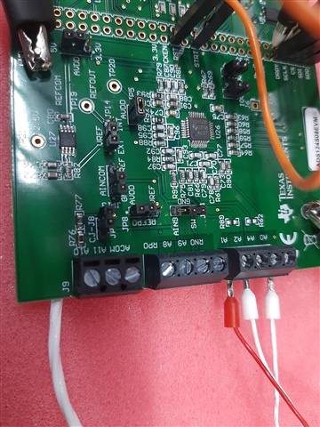
  • Hi Bob

    Please see below image for your reference.


    in that image you can see the jumper setting and also three wire rtd connection on J7. 

    jumper setting are as follows 

    JP1 short - As we are using LP.

    JP11 - 1-2

    JP8 - 1-2

    JP9 -  2-3

    JP12 - NC

    JP13 - 1-2

    JP14- 1-2

    JP5, JP6, JP7 mounted.

    EVM  to  LP connection 

    SDI       PB8

    SDO     PB7

    CS       GND

    SCK     PB9

    DRDY   PA12

    RESET  PB17

    START  PB16

    Common ground and both powered from laptop USB.

    when I initialize system after power on i got 3.3v at TP19. when I send 0x3A command which i found in EVM board script from TI itself which use to IDAC init I got 2.5v at TP19. but after that voltage drops to 2.1v when I try to config 0x03(PGA) register and then further drops when I configure IDACMUX. i dont know why this is happening.  When i configured 0x05 REF reg to 0x06 i got 3.50v at TP19 and also default value of FCAL register(0x0F) changes to 0x00 automatically.  

    when I read default resister it read properly.

    In above images, left side image show you default registers . and on right side you can see resister after configuration.

    As we are using PT1000 Resister do we need to change R68 and R70? we performed above operation with RTD connected and Without RTD but we got same result. 

    one more thing we tried to use ADS124s08 EVM 3 wire RTD default script which is available in Delta sigma ADC Evaluation software but during test we are not getting  2.5v ref at TP19 and any voltage across R68. please let us know if there is something we can test on EVM so that we will get assurance of  EVM is working fine.

  • Hi Mehul Dabholkar,

    From the screen shots you apparently read the default register setting correctly at the start.  However, there is definitely an issue when writing the registers.  This is why I requested that you send me shots of the WREG communication.  So in short, if the register read appears to work correctly, but after a register write the data is incorrect, then you must be having an issue with the register write communication.  It is always better to debug with an oscilloscope or logic analyzer as opposed to using the debugging software as the software doesn't tell the whole story.

    If you want me to review the register write code, attach that portion of the code to your next response along with the scope shots of the communication.

    Best regards,

    Bob B

  • Hi Bob.

    As you mention we wrote some resister and read back the same. when I read back, I got wrong result. but when I put some delay in between writing and reading some will read correctly but some still giving me wrong result.  please let me know jumper setting is correct or not. image is already attached in previous reply. I am attaching code for your reference.

    1. i am setting 0x06 at 0x05 reg 

    reading back 0x05 reg and getting correct value 0x06.

    but getting voltage at TP19 is 1.59v

    2.but when I set 0x3A at 0x05 reg.

    reading back same 

    Getting 2.48v at TP19.

    following register is also i was trying to set but we get wrong value on reading.

  • Hi Bob

    forget to attach code file. please look into it i am not doing so much thing just start board with spi config as mentioned and writing some register and reading back .

    4113.code.txt
    main()
    {
    
    //
        delay_cycles(70400);  		//wait for POST operation
    
        SYSCFG_DL_init();    		// init all gpio and spi with spi mode 1
    
        delay_cycles(32000);  		//required min 20ns we provide 1ms delay
    
        regWrite(REF_ADDR_MASK,0x3A);
        delay_cycles(32000);
        regRead(REF_ADDR_MASK);
    
        regWrite(PGA_ADDR_MASK,0x0A);       
        delay_cycles(32000);
        regRead(PGA_ADDR_MASK);
    
        regWrite(INPMUX_ADDR_MASK,0x12);
        delay_cycles(32000);
        regRead(INPMUX_ADDR_MASK);
    
        regWrite(IDACMAG_ADDR_MASK,0x07);    //07// IDAC magnitude set to 1mA
        delay_cycles(32000);
        regRead(IDACMAG_ADDR_MASK);
    
        regWrite(DATARATE_ADDR_MASK,0x14);
        delay_cycles(32000);
        regRead(DATARATE_ADDR_MASK);
    
        regWrite(SYS_ADDR_MASK,0x10);
        delay_cycles(32000);
        regRead(SYS_ADDR_MASK);
    
        regWrite(IDACMUX_ADDR_MASK,0x35);
        delay_cycles(32000);
        regRead(IDACMUX_ADDR_MASK);
    
        readRegs(ID_ADDR_MASK,18,Data);
        delay_cycles(32000);
        regRead(ID_ADDR_MASK);
    }
    
    
    /////////////////////////////////////////////////
    void regWrite(unsigned int regnum, unsigned char data)
    {
        uint8_t ulDataTx[3];
        ulDataTx[0] = REGWR_OPCODE_MASK + (regnum & 0x1f);
        ulDataTx[1] = 0x00;
        ulDataTx[2] = data;
        for(int i=0;i<3;i++)
        {
            DL_SPI_transmitData8(SPI_0_INST,ulDataTx[i]);
        }
    }
    ////////////////////////////////////////////////////////
    
    void readRegs(unsigned int regnum, unsigned int count, uint8_t *data)
    {
        int i;
        uint8_t ulDataTx[2];
    
        ulDataTx[0] = REGRD_OPCODE_MASK + (regnum & 0x1f);
        ulDataTx[1] = count-1;
        transfer(ulDataTx[0]);
        transfer(ulDataTx[1]);
        for(i = 0; i <= count; i++)
        {
            data[i] = transfer(0);
            if(regnum+i < NUM_REGISTERS)
                registers[regnum+i] = data[i];
        }
    }
    ///////////////////////////////////////////////////////////
    uint8_t transfer(uint8_t tx)
    {
        uint8_t rx;
        /* Set up data for the next xmit */
        DL_SPI_transmitData8(SPI_0_INST,tx);
        /* Wait for data to appear */
        rx= DL_SPI_receiveDataBlocking8(SPI_0_INST);
       // rx= DL_SPI_receiveDataBlocking32(SPI_0_INST);
        return rx;
    }
     

  • Hi Mehul Dabholkar,

    The register values from CCS on default and after writing appear to be shifted in the data.  We have no idea what is causing this to happen, so I personally prefer to set some break points and capture the data as it is coming in to see why this might be happening.  

    It is not clear where some of the definitions are being made like for the 'Data' array used for readRegs(ID_ADDR_MASK,18,Data);.  

    Next possible issue is with ID_ADDR_MASK.  This value should be 0 otherwise the data will be shifted in the array to the wrong locations.  Verify that the correct value for 'regnum' is being sent when using readRegs().  Make sure that the array 'registers' is global as you are adjusting the contents.  So instead of reading back 'registers_after' (which I don't even see in your code) just check the data residing in 'registers' where the read register data is being stored.

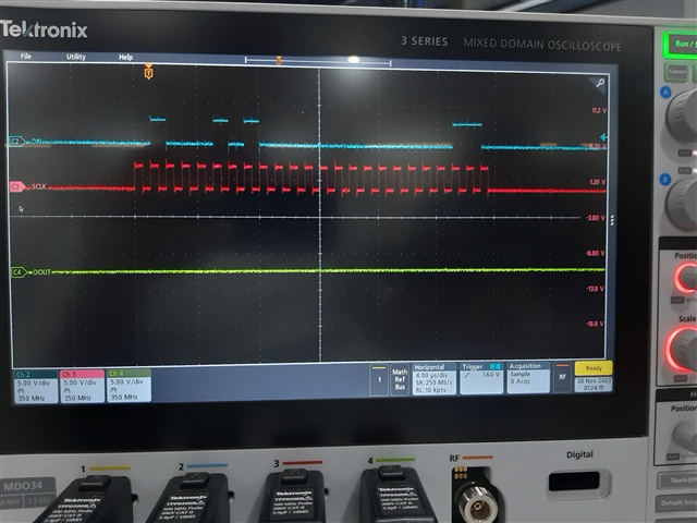
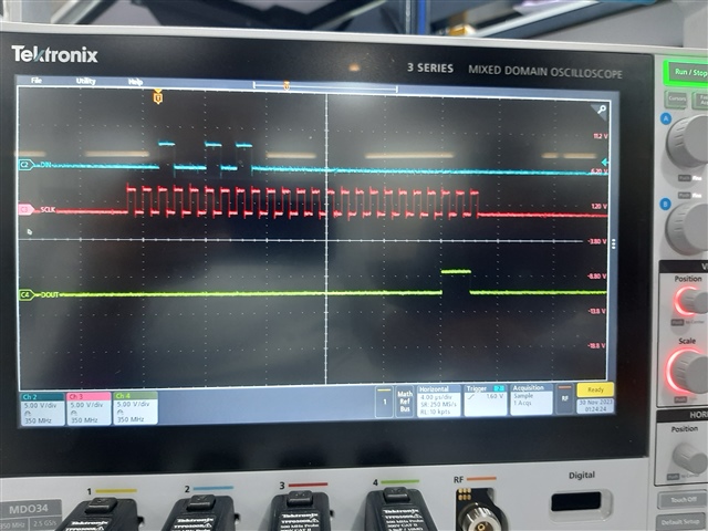
    following register is also i was trying to set but we get wrong value on reading.

    In the scope shots you provided, the first and third plots are register writes (picture is the same) of writing the value of 0x07 to register 0x06.  The second scope plot shows a register read of 0x06 showing the value of 0x07.  So it is not clear to me what you are showing or trying to tell me as the value written is being read back.

    As far as the reference configuration, the main differences between 0x3A and 0x06 is which reference is selected to be used for the ADC conversion and the disabling of the reference buffers.  Can you try sending 0x36 to register 0x05 to see if there is any change if you disable the reference buffers?

    Best regards,

    Bob B

  • Hi Bob

    The ADS124s08 EVM which I am working with I have done some testing on that ADS124s08 EVM. and I run predefined scripts but still i am not getting 2.5v at TP19. also, when I ran those scripts on reading registers i am getting wrong values. please see my screenshots.

    procedure i have done is below.

    1. connect EVM with pc

    2. open deltasigma evaluation software

    3. i am able to read default register data.

    4. run 3 wire rtd script from predefined script.'

    5.data  and register readback 

    Dose my EVM not working ? or do I need to do hardware modification on EVM like jumper setting etc. because same thing is happen when i try to interface EVM with LP(launchpad) .  

  • Hi Mehul Dabholkar,

    Thanks for going back and taking a look at the results from the EVM GUI.  This is wrong on many levels.  First it appears that the EVM is identified as an ADS124S08, but the output data appears to be 16-bit and not 24-bit.  Second, the register map does come back in a corrupted fashion and repeats. So this is very odd indeed and could indicate that the device has been damaged in some way.

    Early on I suggested powering the EVM using the regular USB input, and then adding jumper JP1 when connecting to the LP.  When using the EVM and the GUI, JP1 should be removed.  That would be the only jumper change between using the GUI and the LP.

    Also, when using the GUI the LP should not be connected.  When the LP is used JP1 installed will place the EVM in a reset state and shuts down the communication capability of the onboard processor.

    So one other check with the GUI is to make sure JP1 is removed, then restart the GUI and from the first screen which shows the register settings select the Refresh/Sync button and see what is displayed.  If this appears to be corrupted, then most likely the device has been damaged in some way.

    Best regards,

    Bob B

  • Hi Bob

    Also, when using the GUI the LP should not be connected.  When the LP is used JP1 installed will place the EVM in a reset state and shuts down the communication capability of the onboard processor.

    we followed the same step.

    we always powered on EVM via USB only. But somehow ADC got damaged can we replace onboard ADS chip with new one? is there any other way like hardware testing procedure to check wither my on-board ADC is alive or not? 

  • Hi Mehul Dabholkar,

    If you have the equipment to replace the device you can certainly do so.  However, before attempting to replace the part, I would recommend running the GUI again and right after the GUI has started, press the Refresh/Sync button to see what shows up.  It will be helpful to know if there is some issue that when writing to the ADS124S08 that is affecting the register read back.  It is not clear to me from the scope shots why you can individually write and read registers but there is an error when the registers are read back as a group.  So let's try to troubleshoot this a bit further before replacing devices.

    Best regards,

    Bob B

  • Hi Bob

    I as you said I tested my EVM again and after power on I simply press the button of Refresh/sync after that all resister has been cleared and set to 0. then I execute 3 wire script. but it readback all zeroes it means write operation has not been performed well. I am attaching some screen shots please have look. And instead of writing and reading many resisters at once and have done single resister read and write.But still not able to write single resister.

    below image is showing result after running 3 wire script and then click on refresh/sync button.

  • Hi Mehul Dabholkar,

    This is very strange and something I have never encountered before.  Have you verified that the AVDD, DVDD, IOVDD are all at nominal operating voltages?  Also have you checked to make sure that RESET is being pulled high?  Do you have anything currently connected to the J3 connector that may interfere with the GUI communication?

    Outside of adding headers to the EVM, have you made any other modifications to the board?

    Getting all zeroes back on the initial register read from Refresh/Sync would indicate that the device is in a reset state by either having a missing power supply or the reset pin is floating or not pulled high.

    I am very confused by the differences we are seeing between the EVM/GUI operation and the external processor operation.  We need to verify that there is not a code issue as it relates to the hardware.  Can you take an oscilloscope shot of the GUI communication writing and reading a single register from the main GUI page  (or from the Console using the WREG and RREG commands)?  Then post the pictures of what you sent via GUI and the corresponding scope shots of the SPI communication.  Do this after repowering the board and restarting the GUI.

    Thanks,

    Bob B