This thread has been locked.

If you have a related question, please click the "Ask a related question" button in the top right corner. The newly created question will be automatically linked to this question.

Reading out ADS7841

Other Parts Discussed in Thread: ADS7841

Hello,

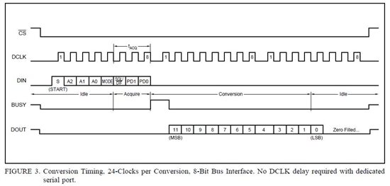
I'm trying to read out the converter ADS7841 in the "24-clocks per conversion" mode. According to the data sheet, the control bits are sent during the first 8 clocks (see bottom). During this time, there should be no data on the DOUT pin. But in my case there is (compare figure). The start of the DOUT signal varies by a few cycles but is always earlier than described in the data sheet. I would be glad if somebody could tell me if this is usual or why it is like this?

Yellow: #CS, blue: DOUT, purple: DCLK, green: DIN


  • Ok the transmitted data fits if I only regard the last few clock cycles so I think it's not completely correct in the data sheet.

    But the next problem is already waiting: I have on one channel the measurement of a high voltage (~400V) via a voltage divider. If I connect the voltage divider the ADC measures about 300mV (although there is no voltage connected from external) what totally spoils my measurement (see picture below, channel pin voltage yellow).

    If I have nothing connected to the channel pin there are voltage peaks (of over 3V!) on the pin, every time the channel is selected (see picture below, channel pin voltage yellow). So the peaks definetly come out of the ADC.

     If I connect the pin directly to GND there is no problem. But the voltage divider's resistor to GND is 16k so the peaks are smaller (compare picture 1) but still present and spoil the measurement.

  • Hi Tobias,

    Can you include the BUSY output in perhaps the last screen shot you posted?  It would be interesting to know if the ADS7841 is properly syncronized to your start command.  Have you looked over this application note?

    http://www.ti.com/lit/an/slaa256/slaa256.pdf


  • Hi Tom,

    thanks for your reply. Here the last screen shot zoomed in and with measured BUSY Pin:


    I had seen the application note but it's for 15 clock cycle mode and I want to use 24 clock cycles.

  • Hi Tobias,

    The channel with the ~400V via voltage divider, can you provide a schematic for this input?  Do you by chance have a buffer between the divider and the ADS7841?  Here is another application note that you might find useful - Designing SAR ADC Drive Circuitry