This thread has been locked.

If you have a related question, please click the "Ask a related question" button in the top right corner. The newly created question will be automatically linked to this question.

ADS1293: Multi-chip design AC Leads-off Detect Synchronisation

Part Number: ADS1293

Hi I'm working on an ADS1293 Multi-Chip design.

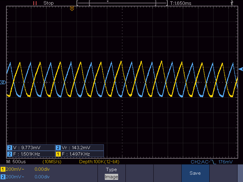
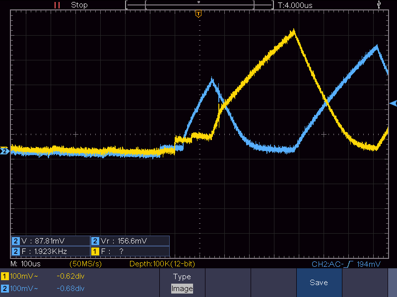
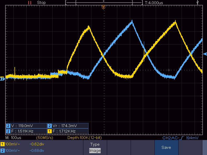
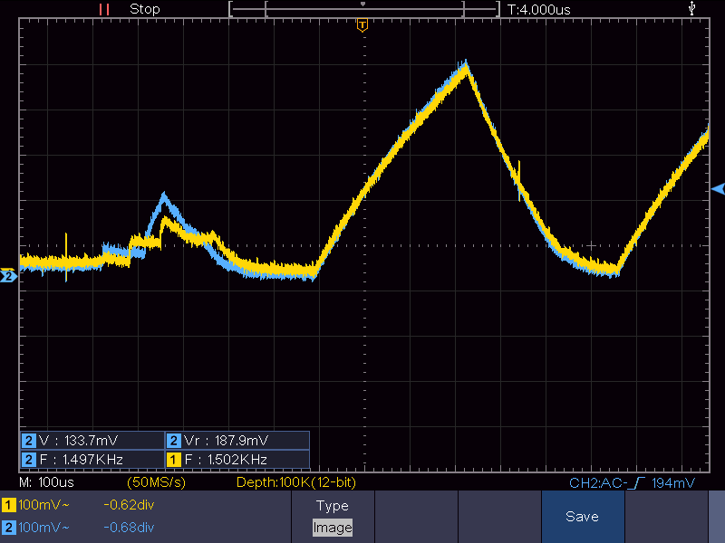
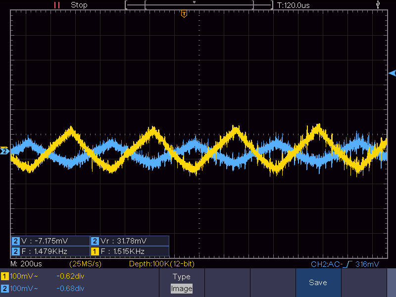
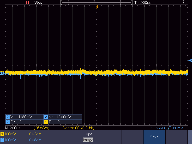
I have run into an issue with the AC lead off detection. The design involves a cable that houses the ECG input wires and since they are close together, there is some crosstalk occuring. Normally this wouldn't be an issue on a single chip design because the AC excitation currents are synchronised and are in phase. However, with a multi-chip design, it seems that the excitation current is not synchronised between chips. This leads to an inconsistent phase difference in excitation current and can result in cases where they cancel each other out through crosstalk. This causes the amplitude to drop below the programed Lead-On threshold producing a false Lead-On.

I've been able to work around this by adjusting the lead-on thresholds and AC frequencies so that they are different in each chip and are less likely to fully cancel each other out through the cable. Though I was wondering if you have run into this issue before and if it is possible to synchronise the excitation current bewteen chips. If not, can you suggest other alternative work arounds?

Regards

David

  • Hi,

    what does "a cable that houses the ECG input wires and since they are close together " mean?

    What type wet or dry electrodes do you use?

    And, which AC lead off detection method do you use?

    8.3.17 Analog AC Lead-Off Detect

    or

    8.3.18 Digital AC Lead-Off Detect

    Thanks

  • Hi,

    There is a wire that is connected to the INA input of the ADS1293 at one end, and the other end of the wire interfaces with the electrode through a resistor. This is the case for the other INA inputs of each ADS1293 chip. Each of the wires are insulated but have been twisted together inside a shielded cable. Since the wires are within close proximity to each other, there is some crosstalk occuring between the wires. That is, the excitation AC injected into one input can be seen on another.

    At this stage the crosstalk and its effects can be seen without connecting any electrodes to the body or simulator.

    Analog AC Lead-Off Detection is being used.

    This is the excitation current comming from the different ADS1293 chips, showing they are out of phase.

    Regards

  • Thanks for the extra info/detail -

    " Since the wires are within close proximity to each other, there is some crosstalk occuring between the wires. That is, the excitation AC injected into one input can be seen on another."

    and

    "Analog AC Lead-Off Detection is being used."

    Just to confirm -  Do you follow - "To operate the LOD in analog AC LOD mode, the SELAC_LOD and the ACAD_LOD bits of the LOD_CN register
    must be set to 1." ?

    Do you use RLD electrode?

    note that -

    "The lead-off detection circuit requires a low-impedance return path from the right-leg electrode-to-ground, such
    as a voltage reference or the RLD amplifier output."

    ----------------------------------------------------

    Does the cross talk waveform you showed also appear in the ADS acquired signal?

    And

    Do you also see this cross talk issue when connect to an ECG simulator?

    Can you show the waveforms comparison side-by-side  connected to ECG simulator vs not connected to ECG simulator?

    -----------------------------------------------------------------------------------------

    Maybe try adjust different excitation frequency or lower amplitude.

    -----------------------------

    You may want to improve or try different cable design.

    Thanks

  • Thanks for your response

    Yes, the correct registers are set for AC LOD. Currently RLDOUT is routed to one of the inputs as the RLD reference, so no dedicated RLD electrode. It's another issue with the cable in that the capcitance between the twisted wires provides an AC return path which also lowers the amplitude.

    ----------------------------------------------------------------------

    The waveform does not appear in the aquired signal, as the AC frequency I use is outside the programed bandwidth.

    Here is the AC excitation waveform when the cable is connected to the device but not a simulator.

    Here is when it is connected to the simulator (all leads ON)

    The waveform morhpology is the same in either case, just lower amplitudes as the impedence of the return path lowers. 

    ------------------------------------------------------------------------

    Currently, adjusting these settings is the work around I have looked into, but it makes it hard to design the correct thresholds, alot of trial and error. I was hoping there may be another alternative solution.

    Would you know the process by which the excitation frequency turns on from the moment you program the LOD_EN register? There seems to be variation in how it begins. Here is a few images of when the AC LOD excitation frequency first starts.

    Note that each colour represents the waveform from different ADS1293 chips and sometimes the phases end up matching.

    Regards

  • Hi,

    Thanks for sharing.

    What does it mean in the first screen shot "Here is the AC excitation waveform when the cable is connected to the device but not a simulator."?

    what device are you referring to?

    -------------------------------

    "note that -

    "The lead-off detection circuit requires a low-impedance return path from the right-leg electrode-to-ground, such
    as a voltage reference or the RLD amplifier output.""

    Don't screenshot 1 and 2 give some clue and info to tell Lead On vs Lead Off?

    Could you show a picture or drawing or diagram how you probe those two signals?

    -------------------------------

    Does the cross talk waveform you showed also appear in the ADS acquired signal?

    -----------------------------------------

    Regarding to "Would you know the process by which the excitation frequency turns on from the moment you program the LOD_EN register? "

    Could you explain more what you mean?

    Thanks

  • Hi,

    To clarify, by device I mean the ADS1293 chips. So there are 3 states in which I observe the excitation AC waveform. I observe this by probing the IN3 pin of the first ADS1293 chip (Blue) and the IN3 pin of the second ADS1293 chip (Yellow). The ground of the probe is connected to the ground of the ADS1293 chips.

    Note that when I mention lead ON/OFF status, that is with the probes diconnected.

    The first state is when nothing is connected to the inputs of the ADS1293 chips. The excitation waveform looks as follows where each colour is an input from different ADS1293 chips. In this state, all inputs are leads OFF.

    The second state is when the inputs of the ADS1293 are connect to the wires that are twisted togther (the cable), introducing cross talk. The other end of the wires are not connected to anything. In this state some inputs can go leads ON.

    The third state is the same as the second, except the other ends of the input wires are connected to a simulator. In this state all inputs are leads ON.

    --------------------------------------------------

    The crosstalk waveform does not appear in the ADS aquired signal.

    --------------------------------------------------

    So my understanding is that the excitation AC only starts getting injected when you program the appropriate bits in the LOD_EN register. My question was about what happens internally when that happens. Are there any delays? Is there some synchronisation between chips (using the SYNC pin)?

    My screenshots then showed the moment the LOD_EN register was enabled on each chip, I was wondering if this is expected behaviour as there seemed to be some variation.

    Regards

  • Hi,

    Let me understand you correctly,

    So, when you use twisted pair, it could detect Lead ON even though the lead is actually OFF?

    Have you tried without twisted pair and/or separate them apart?

    -----------------------------------

    So do you want to know whether there is delay between when you turn on LOD_EN to the AC excitation starts injecting?

    I believe there could be some clock delay, for the exact delay, I will need to ask other engineers and get back to you.

    -------------------

    how many ADS1293 do you use? 2 or more?

    How do you connect(connection topology) them to your host/master? All independent in parallel?

    Did you follow datasheet 9.2.3 8- or 12-Lead ECG Application?

    Thanks,

  • Hi

    Yes you understand correctly, the issue I believe is a mixture of crosstalk and a capcitive return path to RLD reference through the twisted wires. The issue does not occur when wires are completely separate. It is easier to compensate for the return path, but since the crosstalk is not consistent, it becomes harder to work around.

    One solution, as you said, is to change the design of the cable, though I was trying to explore other options that may be suitable.

    -----------------------------------

    Yes , I'd like to know what occurs from when you first program LOD_EN. I'd like to confirm if the delay or something else is the cause of the inconsistencies as sometiems the excitation AC frequencies are in phase and sometimes they are not.

    -----------------------------------

    At the moment I use two ADS1293 chips and I follow the topology in datasheet 9.2.3 8- or 12-Lead ECG Application. In future I'd like to scale this up to using three ADS1293 chips, though I can see this crosstalk issue being even harder to work around.

    Regards

  • Hi David,

    I checked with the team and unfortunately, we don't have any design details about the delay between turning on LOD_EN to the AC excitation starts injecting.

  • Hi,

    Thank you for checking. Would there be any information on how the AC coupled synchronous detector mentioned in 8.3.17 Analog AC Lead-Off Detect works when two frequencies are present in the signal? At the moment I'm using 1.5 kHz and 2.0 kHz, and both are present on each input pin due to crosstalk and capacitive connections.

    Otherwise can you suggest any other alternatives to deal with the excitation AC synchronisation issue outlined previously?

    Regards

  • Hello David,

    I will have to check with my team and get back to you. Because of Thanksgiving holidays in the US this week, I will have to get back to you by Tuesday or Wednesday next week.