Hello everyone,
I've been experimenting with the ADS1299 Evaluation board, aiming to measure a one-lead ECG while incorporating a bias electrode into the setup. Here are the modifications I've made to the default jumper settings:
- JP1: 1-2
- JP2 (AVDD +2.5V): 1-2
- JP20 (AVSS -2.5V): 2-3
- JP6: 2-3
- JP25: Removed all jumpers
- J6: Removed jumpers 5-6, 7-8.
Additionally, I adjusted the resistor value of R8 to 100K Ohms based on suggestions to enhance the bias amplifier bandwidth and reduce 50Hz powerline noise.
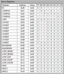
RA electrode is connected to J6(6), LA electrode is connected to J6(8), and the bias electrode is connected to JP25(2). For further clarity, I've attached images of my application settings.


I have a few questions:
-
Can you please review my setup and settings to ensure correctness?
-
I've observed that when using a higher gain, the powerline interference of 50Hz increases. Any insights into this phenomenon?
-
Interestingly, connecting the bias electrode to my body reduces the 50Hz powerline noise by 18dB. Is this an optimal result, and are there ways to further improve it?
I appreciate any guidance, feedback, or suggestions the community can provide. My goal is to adapt this EEG-centric evaluation board for ECG measurements.
Thank you for your assistance!
Best regards,
Gennady

