This thread has been locked.

If you have a related question, please click the "Ask a related question" button in the top right corner. The newly created question will be automatically linked to this question.

ADS1299: Daisy Chaining with internal clock gives garbage data on second ADS

Part Number: ADS1299


Hi,

We have been trying to configure 2 ADS1299 in either Daisy Chain or Cascade Mode. Our preference has always been Daisy Chain as it saves us pins.
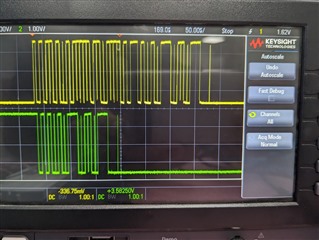
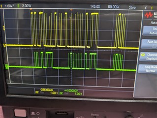
We have made the connections as mentioned in the section 10.1.4. Both the ADS work well individually, but once we put them into Daisy Chain(order does not make a difference), we are constantly getting garbage data from the second ADS. The values does not change even after touching the input channels. We have already probed the CLK and SCK and found both of them to be well synchronized. Both the ADS share their DIN, SCK, CS and RESET pins. Also, on probing the DOUT of both the ADS we notice something strange, the second ADS sends its data twice. In the attached image, Yellow is the DOUT of the first ADS and Green is the DOUT of the Second ADS.

1. What could be the reason that the second ADS gives out the data twice?

2. Why does the values not change even after touching the inputs?

  • Update:
    1. The same does not happen when using external clock. Image attached.

    2. The values are now changing when we touch the sensors, but still not as stable as the first ADS.

    Are there any limitations when using internal clock? What could be the possible reason for this behavior?

  • Hi,

    In daisy chain configuration, you will be primarily looking at the DOUT of the first device which would be connected to the host processor.

    Since the 2nd device receives 2x the number of SCLKS, the data will repeat on the DOUT of the second device which is connected to the DAISY_IN of the first device.

    This shouldn't affect the data since the host processor should only provide 2x clocks to read out the data.

    Can you feed in some external test signal like sine wave on selective input channels and check the data output?

  • Hi,


    1. What do you mean by "2nd device receives 2x the number of SCLKS" ? As per my understanding since SCK is shared both should receive the same SCK and be in sync. Can you also explain why this does not happen with external CLK. If possible please provide some references

  • Hi,

    Whenever you use multiple ADC devices, it is recommended to use only one clock source for best synchronization. Hence I went with the assumption that you are already using an external clock to both devices.

    I have not come across this scenario in the past with the internal clock for daisy chain configuration. Can you share your schematics? If you do not want to share your schematics in a public forum, please send it to ads129x-support@list.ti.com

    If you need to use the internal oscillator in a daisy-chain configuration, one device must be set as the master for the clock source with the internal oscillator enabled (CLKSEL pin = 1) and the internal oscillator clock brought out of the device by setting the CLK_EN register bit to '1'. This master device clock is used as the external clock source for other devices.

  • I understand what you mentioned regarding the use of internal and external clock. I am using internal clock and I am able to get data from both the ADS. Data is stable. Only issue is the data from second ADS is a little saturated. I will try to solve that, if not I will reach out to you on the above mentioned email.

    What I wish to understand is what you mentioned :

    Since the 2nd device receives 2x the number of SCLKS, the data will repeat on the DOUT of the second device which is connected to the DAISY_IN of the first device

    Please provide me with the references.

  • Hi,

    Regarding the 2x SCLKS, I was referring to 2 devices in Daisy chain mode getting 2x SCLKS to read data out from both the devices. Refer Figure 71.

    In multiple readback feature, data is read out multiple times when more SCLKs are provided.

    I assumed that this was what was happening in Daisy chain mode for the second ADS when it received more SCLKs. Looks like this is not the case.

  • Thanks for the explanation.

    I had one more doubt. Now that our data is stable, the data from first ADS is pretty normal and gives us good EEG, but the values from the second ADS are saturated. I believe this is because of incorrect configuration of BIAS.

    I have shorted the SRB  and BIASINV of both the ADS together and the BIAS biuffer of the second ADS is powered down. Can you help me with the correct connection of BIAS?

  • Please share your schematics and device register configuration to review.