This thread has been locked.

If you have a related question, please click the "Ask a related question" button in the top right corner. The newly created question will be automatically linked to this question.

ADS1285: Register programming problem

Part Number: ADS1285

Hi, team.

I'm having some problems with registers' configuration.

"write_ads1285_register()"is the function I use to write all registers;

"write_single_register(adress,data)"is the function I use to write single register;

"read_ads1285_register()"is the function I use to read all registers;

they transmit through SPI

{0x40, 0x0D, 0x00, 0x12, 0x00, 0x32, 0x03, 0x00, 0x00, 0x00, 0x00, 0x00, 0x40, 0x00, 0x00, 0x80}

{0x20, 0x0D, 0x00, 0x00, 0x00, 0x00, 0x00, 0x00, 0x00, 0x00, 0x00, 0x00, 0x00, 0x00, 0x00, 0x00}

these data is written to the registers/ to read Configuration

write_ads1285_register();

while(1) {read_ads1285_register();}

what I got is:00 12 00 32 03 00 00 00 00 00 40 08 00 80 

that means GPIO0_DAT[3:3] is HIGH mode ,

and I cannot change it unless I send codes below:

write_single_register(0x4b,0x02);
read_ads1285_register();
write_single_register(0x4b,0x00);
read_ads1285_register();


and I got these:

00 12 00 32 03 00 00 00 00 00 40 02 00 80

00 12 00 32 03 00 00 00 00 00 40 00 00 80

If I only do this after I got a "08" for GPIO0_DAT[3:3] 

write_single_register(0x4b,0x00);
read_ads1285_register();

what I got is still "08"

Isn't the default value of this register 0x00?Does it have any special meaning for "08"?

  • Hello Xingwitt,

    Writing 02 to the GPIO register configures the GPIO pins as inputs.  When you read the value back, you are reading the state of the GPIO pins in this case for bits [4:3].  When you write 02 to this register, you have now configured GPIO0 as an output, and reading this bit will always equal what you write to it.

    Based on the behavior, I assume the GPIO pins (15 and 16) are not connected to anything and when configured as an input, they are floating.  Depending on leakage currents, the bits in the GPIO register can read 0 or 1.

    Regards,
    Keith Nicholas
    Precision ADC Applications

  • Hi team,

    Thanks for solving my problem.

    I wanna use both channels of ads1285, and when I tried to change channel through changing the register configuration,which address is 0x02. MUX: 000b = Input 1  001b = Input 2,I find out that when the time interval to write to the register is less than about 15~25ms, adc's channel output data looks confusing. More specifically, when I want to read channel 1, the output data is: channel 2, or: channel 1 and 2.When the switching time is greater than this value, this phenomenon disappears, which means when I read channel 1, the output data is channel 1

    Can I change this situation to be more time-efficient?

    Regards,
    Xingwitt

  • Hi xingwitt,

    Keith is out for the holidays here in the US, please expect a response sometime during the week of Jan 1

    Thanks for your patience

    -Bryan

  • Hello Xingwitt,

    The ADS1285 uses an internal digital filter, and when changing channels, you must allow this filter to fully settle.  If you are using the SINC+FIR filter, then you need to allow 66 sample rate periods to fully settle.  If you have the data rate set to 4ksps, this will require 66*1/4000=16.5ms.  If you would like a faster settling time, then you would need to use the SINC filter output.  Using High or Mid power mode and DR=0x000b, your data rate will be 8ksps.  The SINC filter will require 6 data rate samples to settle, which will be 6*1/8000=0.75ms.

    Regards,
    Keith

  • Hi Keith,

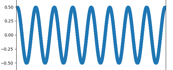
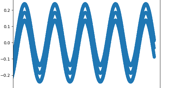
    I give a sinusoidal signal(Single-ended input,-+0.5V) to ADS1285 using the SINC+FIR filter, the output data is -+0.5V sinusoidal signal,which is correct.But when i use the SINC filter, output data looks quite weird--it is a sinusoidal signal where three lines coincide,and the peak-peak value is about -+0.23V,which is incorrect compared with my input.(pictures below using the same input,the left using the SINC+FIR filter and the right using the SINC filter)

    Does it mean that if I want to choose a faster settling time and get the correct output data,I shall configure the register below:

    CONFIG0(address0x01):0x22,which means 4ksps and use the SINC+FIR filter

    CONFIG1(address0x02):0x00,which means input1

    then,

    CONFIG0(address0x01):0x01,which means 8ksps and  6 data rate samples to settle

    CONFIG1(address0x02):0x20,which means input2

    CONFIG0(address0x01):0x22,which means 4ksps and use the SINC+FIR filter

  • Hi xingwitt,

    We need additional time to respond to this question, please expect a response in approximately 1 week. Thanks for your patience

    -Bryan

  • Hi xingwitt,

    We were unable to get to this questions this week, we hope to have a response back to you by Wednesday next week because Monday is a holiday

    -Bryan

  • Hello Xingwitt,

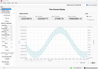
    The ADS1285 uses a dither function to reduce idle tones in the lower frequency passband.  This dither function is basically a 0.25Vpp square wave that is added to the input signal.  This dither frequency is removed when using the FIR+SINC filter option.  Using the SINC filter option is only intended to be used with an additional FIR filter function in the system processor.  Unfortunately, there is not a way to turn this function off, so to use the ADC, you need the FIR+SINC function, which will have a long settling time when switching between channels.

    Below is what the output waveform looks like when only using the SINC filter.

    Regards,
    Keith