Hello,
The datasheet didn't describe the relationship about the input voltage VS output code. For example, if the input voltage is 0.75V , what is the output code?


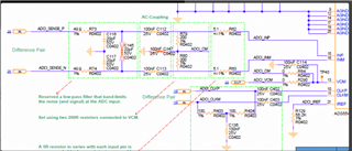
Below is the configuration:

Best regards
kailyn
This thread has been locked.
If you have a related question, please click the "Ask a related question" button in the top right corner. The newly created question will be automatically linked to this question.
Hello,
The datasheet didn't describe the relationship about the input voltage VS output code. For example, if the input voltage is 0.75V , what is the output code?


Below is the configuration:

Best regards
kailyn
Hi Kailyn,
Can you please confirm which configuration is being used. The tables look they are the different options for configuring the part. Is default being used?
Also, is the 0.75 V input a DC voltage?
Best regards,
Drew
Hi Drew,
Thank you for your reply.
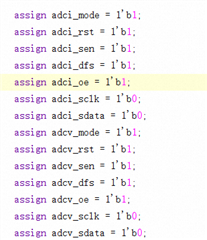
The configuration is as this:

In addition, 0.75Vpp is differential signal.
Best regards
Kailyn
Hi Kailyn,
Thank you for this information.
Are those pin assignments, that I assume correlate to the picture of the tables you sent?
Is "adcv" voltage and "adci" current?
To confirm, dfs being set to 1 denotes "offset binary"?
For the MODE pin, both description boxes say "Internal"...should one of them be "External"?

Best regards,
Drew