This thread has been locked.

If you have a related question, please click the "Ask a related question" button in the top right corner. The newly created question will be automatically linked to this question.

ADC32J22: ADC32J22EVM and HighSpeedDataConverter Pro installations

Part Number: ADC32J22
Other Parts Discussed in Thread: DATACONVERTERPRO-SW, LMK04828, , LMK04832, ADC32J25EVM

Hi support team,

We have just bought the ADC32J32EVM and TSW14J50 data acquisition card. Here are some issues during the installation that I have encountered and solved (?) that I would like to share out and ask for the confirmation if everything is alright before continuing.

1) Installation of of HSDC Pro (Highspeed converter Pro s/w), but when launching it there is an error message of "Unable to locate the LabView Run time Engine", so one needs to go to ni.com to down load the version 2019 and then the HSDC Pro s/w will run without any further error message. By the way I did try to use the Run time engine 2023 first but the error message was still present so I select the older version 2019 (as indicated in the error message) . Can you confirm that only the version 2019 is supported for this HSDC Pro s/w v6.00 ?

2)  There is no dedicated guide page for ADC32J32EVM, and to find the ADC3xxx GUI Installer one need to search though the forum to see (forum 1095918) that one can go to the www.ti.com/tool/ADC3443EVM guide page to find the s/w package SLAC667-ADC3xxx GUI Installer. It would be useful to have a guide page for ADC32J22EVM board.

When launching the ADC3xxx GUI it will try to load the missing ftd2xx.dll file from the directory instr.lib (that does not exist when one installs the GUI package). This problem has been raised many years ago in the ADC forums, so I create the instr.lib directory under the directory ../Texas Instruments/ADC3xxx and to place the file ftd2xx.dll there.

Now, where to find this file ftd2xx.dll that will make the GUI working as expected will need many tests.

Data-converter-forum/685110 showed that this file ftd2xx.dll can be obtained from the DATACONVERTERPRO-SW, but once I find & place this file in the instr.lib directory, the missing .dll file message will then be loaded, but there is other error message (?) 
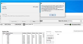
If one ignores this message, the GUI will open but it does not work properly because one can not select other devices, the tap ADC34Jxx does not change, because I would like to set to ADC32Jxx instead
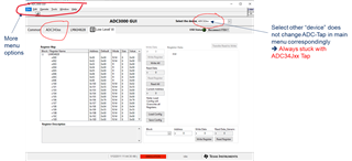
In the forum 1260159, Eric Kleckner has included a ftd2xx.dll in his attached simple_api.zip, so placing this file into instr.lib directory there is no more issue of loading the dll file. The GUI appears to work correctly because changing device will lead to the corresponding ADC Tap as shown below. I hope that the "FTDI not connected" message will disappear once I power and connect the EVM board.
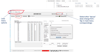
A third way to get the ftd2xx.dll is to follow the guide in the ADC3xxx/Documentation/ADC3xxxManifest.html

So I take the one from ../System32/../..i386 and put this under instr.lib and again the ADC3xx GUI is working as the solution given by Eric K.
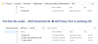
Going through this installation, few questions arise before I power up the EVM and control it with the installed sw packages:

1) Can you confirm of my installation ? 

2) Why the ftd2xx.dll from HSDC Pro does not work as expected and its GUI menu is different from the other .dll that seems to make the ADC3xxx GUI working ?

3) Do you have the config file for my ADC32J22EVM board because under the ADC3xxx/Configuration Files directory, there are only .cfg files for 40, 80, 120 and 160MSPS ?

4) Does my EVM board have LMK04828 clock source or do I need to provide the board with an external sampling clock ?
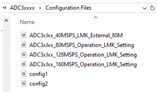
Thanks in advance for your support.

Kind regards,

Minh Nguyen

  • Sorry that few typo error is coming for the part number in my message test,  it should read ADC32J22EVM  (not ...32EVM)

  • Hi Minh,

    We have recently noticed that some machines are not installing version 6.0 correctly so I am attaching an older version which should not have these issues. There should not be any need to move any dll files around when installed correctly. We are looking at fixing this issue and will re-release whenever the issue has been solved. Until then, please install and use this version instead.

    TI Drive: https://tidrive.ext.ti.com/u/_c00lcVNNNHvzTSS/2f3bd4de-1827-4da1-a0b7-805d75cb10c6? 

    Access Code: UfD9Q?6J

    I am checking on the LMK configuration files. My installation of the GUI does not have these so I am reinstalling with the latest version onto my lab PC. I will update shortly.

    Thanks, Chase

  • Hi Minh,

    I have taken a look at the 80MHz configuration file and it seems that the LMK04828 is using the 100MHz onboard reference to generate a VCO0 frequency of 2560MHz. The LMK CLKout0 divider is set at 32 providing an 2560/32=80MHz signal to the ADC, and the CLKout2 divider is set at 16, providing a 160MHz signal to the FPGA. The problem here is that the maximum divider value of 32 and the minimum VCO frequency is too high. The VCO frequency must be an integer multiple of 50MHz up to 32, but this is not achievable using the LMK04828 as the minimum VCO frequency will be 2370MHz. If we divided this 2370MHz by 32, the absolute lowest output frequency supported with onboard mode for LMK04828 is going to be roughly 74MHz.

    Attached is a configuration which sets the LMK into a divider mode. In this mode, the FPGA reference clock is passed through without division while the ADC clock is the input clock divided by 2. I believe this is what is required for this device but have not checked it myself. Please give this a try: ADC3xJxx_50MSPS_Operation.cfg

    Thanks, Chase

  • Hi Chase

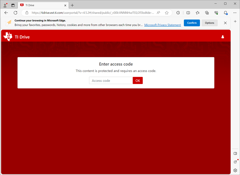
    Thanks for your fast reply, but I have difficulty to access the TI drive to load your file, it asks for login using  TI Entreprise or ENt.TI.COM with userID and password !

    I have only account for TI E2E to access forum Q&A. Is the above needing a creation of a new account ?

    Thanks,

    Minh

  • Hi Minh,

    It should not ask for those details. Can you try using a different browser perhaps? I have just checked on a browser which I am not logged in and see the correct page. It should look like this:

    Thanks, Chase

  • Hi Chase

    The .cfg is blocked by our company firewall. could you zip the file instead and send again ?

    BTW, does my ADC32J22 have to work with 50Msps exact or can it work at other freq than  50Msps such as 40MHz instead  (=2560/64) ?

    BR,

    Minh

  • just read again to see that the max divider value is 32 so my question of divider by 64 does not apply

  • Hi Chase

    unfortunately when I copy your link  over 2 different browsers (Chrome and Edge) it gives the same issue 

    tidrive.ext.ti.com/.../2f3bd4de-1827-4da1-a0b7-805d75cb10c6

    Since the link does not have the full path as shown in your photo so it may cause the issue ???

  • Minh,

    Find attached again in zip format: ADC3xJxx_50MSPS_Operation.zip

    This ADC specifically can operate at any frequency between 10MSPS and 50MSPS. The 10MSPS lower limitation is due to the JESD204B interface. See section 9.3.5.3 JESD204B Frame Assembly in the datasheet for more details. 

    The divider of 64 is possible using LMK04832, which is a pin to pin compatible device. The register map is not the same as the LMK04828, however if you are capable of replacing the LMK04828 with the LMK04832 device on the EVM board, we can provide assistance in creating a configuration for you using that device.

    Thanks, Chase

  • OK, it works now for the link ... copy from my mail and the one from this page gives different result !

  • Hi Chase

    The download of the older version HSDC Pro 5.2 is OK on my side (its size is smaller 595 Mbytes), I will install it and let you know if this is OK or not.

    BTW can it be installed in parallel with version 6.0 or not ? The version 6 (size 1 Gbyte, twice as big as the 5.2 version ??!!)   is installed into Program Files/Texas Instruments

    2) Now for the installation of ADC3xxx GUI Installer (slac667d) for setting the cfg of the EVM board itself, it is installed into Program Files(x86)/Texas Instruments, here the package also includes another directory of High Speed Data Converter Pro, but inside it just has one directory Device GUIs !

    I will add your 50MHz_operation config file into ADC3xxxx/Configuration Files and test it out.

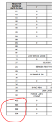
    3) for the config file of ADC32J32 the register address goes up to 0x70A

    but in the data sheet of ADC32Jxx (rev June 2015) there are registers at address 0x422/434/522 and 534 but no 0x70A address ... they are not inside the provided cfg file. 

    Should we ignore them ? or is the data sheet not up-to-date ?

    Regards

    Minh

  • Hi Chase

    Unfortunately we do not have the ability to replace the LMK04828, 

    For your 50MHz cfg file, it mentions of an FPGA reference clock ... do you mean that the LMK is effectively by-passed and we use an external reference clock instead ?

    What is the frequency of the FPGA ref clock ? 100MHz ? then ones does div-2 to give 50MHz to ADC ?

    BR,

    Minh

  • Hi Minh,

    Yes, these can be installed in parallel. This version (5.2) is installed into the x86 program files path and operated on 32 bit. The v6.0 is a 64-bit version. I use both daily on my system in the lab and there is no issue installing both of them in parallel.

    Regarding the register discrepancy between the GUI and the datasheet, anytime this occurs, the datasheet will contain the most up to date information. In your case, you can simply add these onto the end of the configuration file with the settings you desire.

    Regarding the replacement of the LMK04828: That is fine and understandable. The configuration I have sent places the LMK into 'distribution' mode. The signal into the input CLKin1 will be fed directly to the divider stages for each output. The frequency relationship that the FPGA reference is twice as fast as the ADC sample rate is something I inferred from the 80MSPS configuration file. This is specific to the FPGA firmware PLL ranges and LMFS configuration. If you use LMFS=2221, then the FPGA reference clock will be twice as fast as the ADC sample rate. This configuration file requires that the clock input into connector J10 is 100MHz (or double whatever your desired ADC sample rate).

    Thanks, Chase

  • What is the frequency of the FPGA ref clock ? 100MHz ? then ones does div-2 to give 50MHz to ADC ?

    Your logic is correct. The FPGA will receive double the ADC clock because the FPGA divider is half of the ADC divider. The sample rate can be adjusted (in this case of LMFS=2221) between 15MSPS and 50MSPS. Whatever the desired sample clock is, you will need to provide the 2x this sample rate frequency into the EVM connector J10. 

  • Hi Chase

    I will try to look in detail what LMK device is soldered on to my ADC32J22 EVM board. I reckon that since this ADC EVM is provided with the on board clock circuitry then  this clock tree must support the corresponding ADC being used on this same EVM board. Would you think so ?

    If this is the case then somehow TI should provide the corresponding (a typical) cfg file for user to test out the chosen ADC on this EVM board.

    Also I will need this clock tree to work because the ADC EVM will be connected to the other acquisition board TSW14J50 so it will get all the clocking from the FMC connector.

    Thanks

    Minh

  • Hi Minh,

    You do not need to look as the LMK04828 will be what is installed on your EVM. This was the BOM option for this EVM.

    The EVM still supports the operation at 50MSPS, it just requires an external clock. The LMK04832 was not created when this EVM was made, so it simply could not have been used. Again, the clock tree works, you just need to supply 100MHz instead of supplying nothing.

    What I can do for you is check if it's possible to send you a modified version of the ADC32J22EVM (with the LMK04832 instead) so you can use fully onboard clocking with the newer clock device. If this is something you would like, please let me know and I can check with the team on this.

    Thanks, Chase

  • Hi Chase

    Thanks for confirming that the LMK04828 (I can read the printed marker of the device soldered on too) on our board can not be used with the ADC32J22.  From the printed info this EVM PCB board was created in 2014 with marking as ADC32J22 EVM (board ref number 3863600158),

    The ADC itself has printed part number as XAZ32JXX TI 4BJ PHJK G4. We bought this board just before the end of last year 2023 through the distributor Mouser France so I wonder if it is possible to exchange this board with the version having the appropriated clock tree from LMK04832.

    In the case that we can not do so, this EVM board has the option Ext ADC in via an SMP connector, so it may be a better idea for us to us this path to provide the external clock (10MHz to 50MHz of a low noise low jitter signal generator) for the ADC.

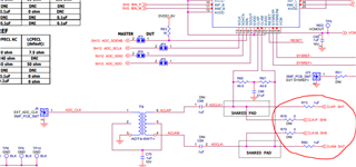
    In this case can you confirm that I will need to remove the R73, R76, R79, R80 as shown in the schematic ADC32JXXEVM-SCH_C.pdf ?

    In the case of using an ext ADC clock, do we still need to program the existing LMX04828 for using with the data acquisition card TSW14J50 & with the HSDC Pro program ?  Can your previously sent 50MHz_operation cfg file be used as such without any further modification ?

    3) Can you also confirm that my method of installation the ADC3xxxx_GUI as mentioned in the first mail is correct as your set up ?

    Thanks

    Minh

  • Hi Minh,

    There is not a version with a newer part. What I was offering is to personally swap the LMK04828 with the LMK04832 and then ship to you. Returning the board you have to the distributor would not do any good.

    To use the ext adc clock input option, you would remove R73, R80 and also install C68, C69. (R76 and R79 are already not installed). This option allows you to supply the ADC with a clock with better performance than the LMK048xx. However, provided that you are only operating the LMK048xx in distribution mode, the only additive noise from the LMK048xx will be the divider stage, which is minimal. The ADC performance will not be degraded much if at all. When the ADC is clocked directly, the LMK still must provide the reference clock and sysref to the FPGA as well as sysref to the ADC. I believe the best mode for operation right now is to provide the 100MHz (or twice as fast as ADC sample rate) into J10 and use the configuration file which I have sent previously.

    Regarding the GUI, I would install this version off of the ADC32J25EVM page to be sure. https://dr-download.ti.com/secure/software-development/gui-for-evaluation-module-evm/MD-nfkQLMUchE/01.00.00.0D/slac667d.zip 

    Thanks, Chase

  • Hi Chase,

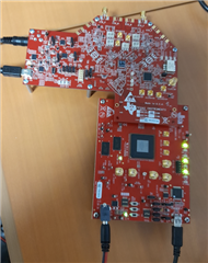
    All the s/w installation appears to run smoothy on our lab PC now (with ADC3000 GUI and HSDC Pro ver5.2) and the boards are connected well to the control sw GUIs, see the photo below. I can write/read/load cfg file to the ADC and LMX devices via the ADC3000 GUI.

    The next step is to get the clock tree working with preferred frequency so that the TSW14J50 can start capture data.

    With HSDC Pro GUI, I choose the option ADC32Jx_LMF_222 as the name is closest to our device ... what does _LMF_222 mean ?

    Regards,

    Minh

  • Hi Chase

    Just see your message now, because I have not refreshed the TI webpage of our conversation that often ! 

    Yes for the ADC3000 GUI, I do the installation from the file slac667d.zip and then see the issue of missing ftd2xx.dll as I described in my very first message. BTW it is solved now as the tool is working correctly as described in my recent message.

    Next, I will follow your suggestion for clock tree.

    BR,

    Minh

  • Hi Chase

    The option to change the LMX  is appealing. Here in France we can contract out of a service to swap/soldering a device for us on PCB, so either you can send us a part or two LMK04832 then we do the work ourselves or we will send back the board to you for changing it.

    Let me know what is the most convenient way for you. In my view your suggested method is better because you can check our board again to ensure that the ADC is working correctly with the LMX04832 at 50Msps before shipping back to us.

    Let me know the procedure and address for shipping this EVM board to you.

    Thanks

    Minh

  • Hi Minh,

    I will reach out via email shortly with details. For now, I will close this post out and we can continue our conversation over email.

    Thanks, Chase

  • Hi Chase

    Thanks for your super help. My setup and the clock tree is working and I can capture successfully the signal through the ADC32J22 EVM board

    BR, Minh

  • Hi Minh,

    I have tested the board and here are the results showing the board is still function prior to shipping back to you. You may also find this info via our email conversation.

    Please take a look at our email thread and respond with the requested info so we can get this board shipped back to you!

    100MHz into J10, 50MSPS operation using LMK04832, Channel A:

    100MHz into J10, 50MSPS operation using LMK04832, Channel B:

    Fully onboard clocking, 50MSPS operation using LMK04832, Channel A:

    Fully onboard clocking, 50MSPS operation using LMK04832, Channel B:

    Regards, Chase