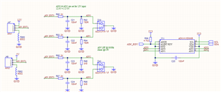
Hello, I am using an ADS1015 to do some basic voltage measurements on two ranges, 0-5V and 0-12V. The ADC VCC is 3.3V, and I am using resistor dividers to adjust both of those inputs into the correct range. The ADC max input voltages are thus kept below VCC at all times. My PGA FSR is set to +/- 4.096V to allow for a full 0-3.3V input to be measured. The same rate is 16 SPS.
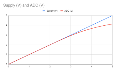
I am seeing good linearity at the lower end of the scale, but as I approach VCC on the input, the ADC measurement deviates and becomes non-linear. See the below chart of the voltage input applied (before the divider on the 5V channel), and the ADC output (scaled at the same factor as the resistor divider to represent the input value).
Why am I seeing this non-linearity, and what can be done to avoid it?


