


Part Number: DAC3484
In our application we are using the DAC3484 component whose function is to generate a 334.7MHz frequency carrier with single sideband modulation with a frequency of 4KHz. The input clock to the DAC (DACCLK) has a frequency of 1229.5MHz.
The DAC is configured with the following sequence of registers in order to generate the 334.7MHz carrier:
ADDR DATA
0 => x"0000" & x"089C", -- 16x interpolator; fifo_ena; alarm_out_ena; alarm_out_pol; clkdiv_sync_ena;
1 => x"0001" & x"050E", -- Even parity; word_parity_ena; quad_ena; alarm_2away_ena; alarm_1away_ena; alarm_collision_ena;
2 => x"0002" & x"8052", -- 16bit_in; mixer_ena; nco_ena; twos
3 => x"0003" & x"F000", -- Default Value
4 => x"0007" & x"D9E7", -- alarm_fifo_collision; alarm_dacclk_gone; alarm_dataclk_gone; alarm_rparity; alarm_lparity;
5 => x"0008" & x"0000", -- Default Value
6 => x"0009" & x"8000", -- Default Value
7 => x"000A" & x"0000", -- Default Value
8 => x"000B" & x"0000", -- Default Value
9 => x"000C" & x"0400", -- Default Value
10 => x"000D" & x"0400", -- Default Value
11 => x"000E" & x"0400", -- Default Value
12 => x"000F" & x"0400", -- Default Value
13 => x"0010" & x"0000", -- Default Value
14 => x"0011" & x"0000", -- Default Value
15 => x"0012" & x"0000", -- Default Value
16 => x"0013" & x"0000", -- Default Value
17 => x"0014" & x"8000", -- AB NCO Freq value = phase_ addAB(15:0)
18 => x"0015" & x"45B0", -- AB NCO Freq value = phase_ addAB(31:16);
19 => x"0016" & x"8000", -- CD NCO Freq value = phase_ addCD(15:0)
20 => x"0017" & x"45B0", -- CD NCO Freq value = phase_ addCD(31:16)
21 => x"0018" & x"280F", -- pll_ndivsync_ena, PLL is bypassed.
22 => x"0019" & x"0840", -- pll_m(7:0); pll_n(3:0)
23 => x"001A" & x"0020", -- Default Value
24 => x"001B" & x"0800", -- fuse_sleep: Must be set to ‘1’ for proper operation
25 => x"001C" & x"0000", -- Reserved Factory Use. Default: 0x0000
26 => x"001D" & x"0000", -- Reserved Factory Use. Default: 0x0000
27 => x"001E" & x"9999", -- syncsel_qmoffsetAB, syncsel_ qmoffsetCD, syncsel_ qmccorrAB, syncsel_ qmccorrCD = Auto-sync from register write.
28 => x"001F" & x"88C0", -- syncsel_mixerAB, syncsel_ mixerCD = sif_sync, syncsel_nco = sif_sync, syncsel_dataformatter = FRAME, sif_sync = '0'.
29 => x"0020" & x"1101", -- syncsel_fifoin = SYNC; syncsel_fifoout = SYNC;
30 => x"001F" & x"88C2", -- syncsel_mixerAB, syncsel_ mixerCD = sif_sync, syncsel_nco = sif_sync, syncsel_dataformatter = FRAME, sif_sync = '1'.
31 => x"001F" & x"88C0", -- syncsel_mixerAB, syncsel_ mixerCD = sif_sync, syncsel_nco = sif_sync, syncsel_dataformatter = FRAME, sif_sync = '0'.
32 => x"0005" & x"0000", -- Reset all alarms.
The data is driven to the DAC on the DATACLKp/n line with a data rate of DACCLK/16=1229.8/16MHz.
When we supply a constant signal (CW), we have the following spectrum output from the DAC.

The -4KHz and 4KHz tones are due to the input clock of the DAC.
When we supply a 4Khz signal on the DATACLKp/n line to have the frequency shift of the carrier, we have the following spectrum:
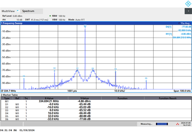
From the figure we can observe some unwanted tones. In particular we observe the tone D2 (-16KHz=-4x4KHz), D4 (16KHz=4x4KHz), D5 (32KHz=8x4KHz) and D6 (-32KHz=-8x4KHz).
By increasing the modulation frequency, unwanted tones are observed to change in intensity. In particular it seems that spurious tones decrease in intensity by increasing the frequency shift.
In the following figure we have the spectrum with a modulating signal at 10KHz.
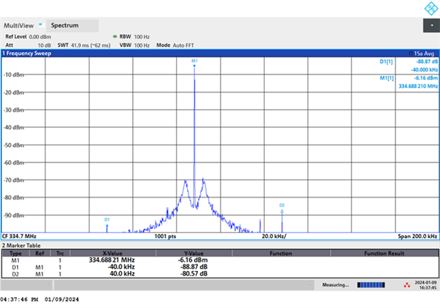
Th spurious tones 32KHz=4x10KHz and -32KHz=-4x10KHz are much lower than in the previous case of 4KHz frequency shift.
Are there any tips to avoid the above spurious tones?
Antonio
