


Part Number: ADS1261-Q1
Hi again,
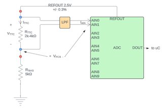
Since the last thread, I've opted for a differential measurement approach to minimize error as much as I can (see diagram below). With this new approach, I'm trying to determine the voltage/temperature resolution the system is capable of measuring. I'm getting confused on how to go about accounting for both DC error sources and noise. Here are the sources of DC error that I've identified in the system.
- RefOut
- Initial tolerance
- Drift/droop over temperature
- Load regulation
- ADC input current
- Typical differential current
- Differential drift over temperature
- Beginning of life resistor tolerances
- TCC sensor
- Bias resistor
- Low pass filter series resistor
- Resistor changes over temperature
- Bias resistor
- Low pass filter series resistor
- Mismatched voltage drops
- PCB traces
- Low pass filter series resistor
- PGA gain error
Based on our previous discussion, I will exclude the RefOut error due to the ratiometric properties of the measurement. Using the remaining RSS'd error sources, I can calculate a worst case range for the thermistor voltage reading across the ambient temperature range. Here, worst case indicates the narrowest range as that would reduce the resolution I'm capable of measuring. Using the datasheet values for temperature drift/coefficients I can approximate a voltage vs temperature curve as well.
In parallel, I've also calculated the noise-free resolution that I've translated into an LSB size. Where I'm getting confused is how I can incorporate the two separate calculations together to arrive at a realistic error-free voltage measurement resolution.
Thanks,
Drew

