This thread has been locked.

If you have a related question, please click the "Ask a related question" button in the top right corner. The newly created question will be automatically linked to this question.

ADS131M02: False data returned when communicate via SPI.

Part Number: ADS131M02
Other Parts Discussed in Thread: ADS131M08

Hello everyone,

I'm currently working on developing the driver for the ADS131M02. However, when attempting to communicate with the sensor via SPI, I consistently receive the response value 0x7F91 when trying to read the ID, STATUS, MODE, etc., which is unexpected.

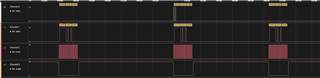
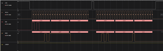
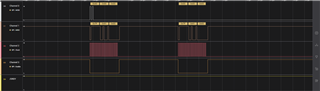
Here is an example that I managed to capture on the wave analyzer:

  • First frame: I attempted to send a NULL command.
  • Second frame: I sent the RREG ID register command.
  • Third frame: I read back the response from the RREG command, which was supposed to return on the next frame.

In my test case, all responses were consistently 0x7F91, and in some instances, the value was consistently 0x0280.

Looking forward to your help, thank you!

Please refer to the waveform below for more information.

  • Hi Thanh Au Duong,

    Have you seen /DRDY pulses from the ADC after it's powered up? What's your SCLK frequency? If you could share your schematic, I can double check for you. You should be able to get a correct response from the ADC because your command is correct, please see the following timing I just captured on ADS131M08 which is 8-ch ADC vs. 2-ch on ADS131M02, 0x2801 was received in the 2nd frame while reading ID register, the response from the ADS131M08 is correct when the same command and similar timing was sent to the ADC.

    Regards,

    Dale

  • Hi Dale Li,

    Thank you for your prompt response.

    I have verified the /DRDY pin, and it appears to be correctly pulled up during the boot-up process. Unfortunately, I still got no luck with the response. You can refer to the waveform below for more details.

    The SCLK frequency I'm using is 1MHz.

    I am using an ESP32-S3 dev-kit to connect directly to the sensor/module for testing, so there is not much to share about the schematic. However, for your reference, I have included the schematic of the module that I am connecting to, hoping it might be helpful.

    Looking forward to your help, thank you!

    Schematic: ADC_15_click_v100_Schematic (mikroe.com)

  • Hi Thanh Au Duong,

    You circuit looks good. Your command is correct to read ID register and also 1MHz SCLK is not a problem, you are also using correct SPI configuration (CPOL=0, CPHA=1). Your /DRDY output from the ADC should continue toggling, not only pulling up, please double check. It would be good if you could share the whole Saleae timing file after the ADC is powered up, /DRDY and /sync/nReset signals should be included as well.

    Thanks&Regards,

    Dale

  • Hi Dale Li,

    Thanks a lot for your help!

    After thoroughly reviewing the data diagram you sent, it appears that the CS pin was pulled down too late. I attempted to resolve this issue by adding a small delay before the CS pull-down and the first SCLK pulse, and it worked!

    Regarding the issue of /DRDY not pulling down, the cause was the due to the lack of a signal on the CLKIN. In my schematic, there is another module (the LTC6903CMS8) that provides the master clock for the sensor, which I'm not yet config. Once I provided an alternative clock source for the sensor, the /DRDY signal was triggered as intended.

    Further note, even without the master clock, I can still send Command/WREG/RREG without encountering any issues; however, there is no data conversion observed on the sensor's end.

    Hoping this information might prove useful for anyone facing the same issue!

  • Hi Thanh Au Duong,

    Thanks for your update. I am glad the issue has been identified. All Delta-Sigma ADCs including ADS131M02 operates with master clock, you should not expect to see any conversion data output from the ADC when your master clock is not available.

    Regards,

    Dale