This thread has been locked.

If you have a related question, please click the "Ask a related question" button in the top right corner. The newly created question will be automatically linked to this question.

AMC3306M05: DCDC_OUT ~1.8V and DIAG pin low when clock disable/enabled

Part Number: AMC3306M05

We are using an AMC3306M05 modulator on a recent board. We have noticed that occasionally, the device would not power up correctly with DCDC_OUT at ~1.8V and diagnostic  pin low. After experimenting with the device, we found that if we disabled the clock (being driven from a microcontroller), the device would come up correctly. We also found that if we enabled and disabled the clock, it would fall back into this failure mode. We have three of these on the board, and all three behaved exactly the same -- that is, if one failed, all failed. So the root cause must be systematic.

We dug through the datasheet, and didn't find anything particular about gating the clock and restrictions around that (other than the amount of time before the output is stable). If I am operating and reprogram the microcontroller, the modulator sometimes lands in this failed state.

Any thought as to why this is happening? What restrictions are there on the clock?

I have seen the other post about the DCDC_OUT being ~1.8V, which sounds like a similar failure, but apparently different issue. Our clock frequency is 12MHz, but during power up/programming I guess it is possible to see a higher frequency for a period.

Thanks!

  • Hi Jay,

    Thanks for your question and bringing this to our attention.

    A few questions for your application:

    1. Is the VDD supply properly established before the clock is applied? 

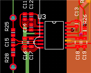
    2. Can you please share a picture of the layout?

    3. Is there any other type of testing happening at power up i.e. surge? 

  • 1. I can confirm this, but I believe so. The same voltage rail is used to power the microcontroller, which drives the clock signal. The microcontroller needs a stable rail as well. Also, I can get this behavior to happen by turning the clock on/off through firmware well after the rails are stable.

    2. The layout is based off the recommended datasheet. I don't believe this is an issue.

    3. No additional testing. The microcontroller powers up and starts running, as well as some other chips. In nominal state, the board draws ~1W; when the failure of the modulator happens, it draws ~2.6W (for all three modulators)! 

    The main question here is what restrictions are there on the clock? Why does turning clock on/off cause this? How can we ensure that it can power up reliably? 

    The best way I have been able to do this is to disable the clock by default and turn it on (once -- multiple on/off breaks it) later in firmware. The best part is that we have three of these all on the same board, and they _always_ behave the same way together. If one is bad, all are bad; and vice-versa.

  • BTW the pullup on the DIAG pin is NOT 49.9 Ohms... that was fixed. 

  • Hi Jay,

    These symptoms sound like latching is occurring in at least one of the devices and causing the lockup. If you can get a scope shot of the clock (with and without failure) with respect to the supply voltage to confirm operation as defined below that should help. Removing or adding in devices 1 by 1 to isolate which of the 3 is latching would help as well - assuming it is layout related. 

    The layout provided immediately next to the device looks good, the clock trace is a little small. How far does the clock have to travel on the board for the 3 devices? 

    If there is a slew rate or under/overshoot occurring on the clock signal soldering a small (~15pf) capacitor from the clock pin to GND may help. 

  • Thanks for the response. Why do you think one is latching? How could this cause the other two to keep DIAG low?

    I can get this behavior to happen just by gating the clock long after all power supplies have stabilized.

    The main indication I have that something is wrong is the DIAG signal. They are three discrete signals to the microcontroller, and all three are either high or all low.

    The clock is from the microcontroller and sent to a fanout chip, which generates the three individual clocks. The furthest clock trace is 4", closest is <1".

    I will poke around with the rails to see timing relationship and stability.

  • Found that the fanout chip is behaving strangely with the microcontroller, causing a slow ramp down when the clock is turned off. This in turn, causes the modulator to latch up. We found a work around and believe that the modulator is functioning correctly.

    Thanks for the assistance. 

  • Thank you for the follow-up Jay. So just to confirm, it was the clocking signal to the AMC3306 that was slowly ramping down and causing the latch up? 

  • Yes that was the cause. When the clock was turned off, it had a 50% chance of stopping at a logic high. When it stopped high, the fanout chip would decay the signal and it would spend 10's of ms in the 1.5V range. The modulator would latch up and drop the DIAG signal early in this decay.

    If the clock was halted at a logic low, there was no issue. Thanks again for the support.