Other Parts Discussed in Thread: ADS1118, ADS1115
Hi,
I am trying to get a PIC18F87J90 controller on a Microchip development board to drive ADS1118EVM with SPI. The issue is that I do not see it convert after the configuration reg has been written to. What I read back from the config reg of the ADS1118 is just the first MSB byte of the config command not the LSB. I can read back the MSB consistently but not the LSB of the config and the data read back is garbage. The inconsistent and incorrect results I am getting are irrespective if i tie CS to GND or drive it with a processor GPIO. I am using UART to post the values I am reading from the SPI to putty so I can see the values being generated by ADS1118EVM in real time.
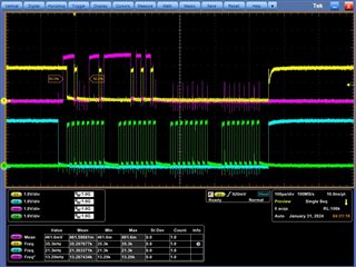
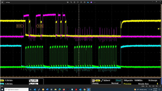
Please take a look at the sample code and the scope caps of the DIN, DOUT, SCLK, and CS. Do you see anything that is not correct as far as SPI interface is concerned? Why am I only getting the MSB of the config write to the ADS back and not the LSB?
Do the config reg and conversion reg have different addresses like with ADS1115 or not? Am I missing something in addressing or command? Do I need to send another command for upload into the config reg after I send the first SPI command to update the contents of the config reg?
If the CS pin is tied to GND, the config reg is set to default. If that is the case does the ADS convert or not? Does the ADS need to be configed externally to make conversions or does it do so with CS low and defaults register settings?
Are there any issues with ADS1118EVM that I need to worry about? Does the ADS1118EVM need to be modified in any way so that it can be driven by an external controller?
In the sample code I am just trying to read back what i write to the config reg. The first two bytes of the SPI write are the config MSB and LSB respectively followed with two cycles of SCLK (DIN set low) used
void main (void)
{

   initializeSystem();   // Initialize microcontroller

While(1){

	SPI_Write2(0x44,0x8A,0x00,0x00);   // writes to the config register

        itoa(adcValue,buffer);		//converts to tring
        EUSART_puts(" Data1 =  ");
        UART_SendString(buffer);	//sends converted string value to UART
        itoa(adcValue2,buffer);
        EUSART_puts(" Data2 =  ");
        UART_SendString(buffer);
	itoa(adcValue3,buffer);
        EUSART_puts(" Data1 =  ");
        UART_SendString(buffer);
        itoa(adcValue4,buffer);
        EUSART_puts(" Data2 =  ");
        UART_SendString(buffer);
}

}

void initializeSystem()
{

    //Primary Oscillator
    OSCCON  = 0b01010100; // 2Mhz sys clock
    OSCTUNE = 0b00011111; // INTSRC <7>: turn off low-freq internal oscillator, "0", PLLEN <6>: PLL enabled, TUNE <5:0>: Maximum freq setting: "011111"
    LCDCONbits.LCDEN = 0; // Disable LCD Driver.

    INTCON2bits.RBPU = 0; // Enable Pull-Up Resistors (needed to use the switches)

    // Setup interrupts
    INTCONbits.INT0E = 1; // enable external interrupt INT0 (RB0) // ****Warning**** Will kill microcontroller's initial ability to MCLR_n (reset)
    INTCONbits.PEIE = 1; // enable peripheral interrupts
    INTCONbits.GIE  = 1; // enable global interrupts
    PIE1bits.RC1IE = 1;   // enable EUSART receive interrupt
    PIE3bits.RC2IE = 1;   // enable AUSART receive interrupt


    EUSART_Init(); // initialize Enhanced Asynchronous USART

    SPI_Master_Init();  // initialize SPI Master


}

void SPI_Write2(unsigned char addr, unsigned char data, unsigned char data2, unsigned char data3)
{

   LATFbits.LATF7 = 0;

  SSPBUF = addr;       //config MSB Write
  while(!SSPSTATbits.BF);
   adcValue = SSPBUF;   //Data MSB coming from ADS Read

   SSPBUF = data;       //config LSB Write
   while(!SSPSTATbits.BF);
   adcValue2 = SSPBUF;   //Data LSB from ADS Read


   SSPBUF = data2;      //can be high or low
  while(!SSPSTATbits.BF);
  adcValue3 = SSPBUF;       //Data MSB from ADS CONFIG1


   SSPBUF = data3;          //can be high or low
   while(!SSPSTATbits.BF);
   adcValue4 = SSPBUF;         //Data LSB from ADS CONFIG2

   LATFbits.LATF7 = 1;

}

void SPI_Master_Init()
{
    TRISCbits.TRISC5= 0;   // RC5/SDO - Output (Serial Data Out)
    TRISCbits.TRISC4= 1;   // RC4/SDI - Input (Serial Data In)
    TRISCbits.TRISC3= 0;   // RC3/SCK - Output (Clock)
    TRISFbits.TRISF7= 0;   // Digital output
    TRISFbits.TRISF6= 0;   // Digital Output
    TRISHbits.TRISH1 = 0;

    SSPSTAT = 0b01000000;        // Set SMP=0 and CKE=1. Notes: The lower 6 bit is read only
    SSPCON1 = 0b10100001;        // Enable SPI Master with Fosc/4 (configure for master)

}

void itoa(unsigned char num, char *str){
    int i =0;
    if (num == 0){
        str[i++] = '0';
        } else {
        while(num != 0){
            int rem = num % 10;
            str[i++] = (char)(rem + '0');
            num = num/10;
        }
        str[i] = '\0';//null terminate
        reverse(str,i);
        }


char EUSART_Init()
{
    SPBRG1 = 25; // Baud rate is 2600 Serial peripheral baud rate generator for 2MHz
    TXSTA1bits.SYNC = 0;    // Asynchronous mode for Tx register
    RCSTA1bits.SPEN = 1;    // Serial port enable for Rx register
    TRISCbits.TRISC7 = 1;  // RX1 enable
    TRISCbits.TRISC6 = 1;  // TX1 enable
    RCSTA1bits.CREN = 1;    // Continuous receive enable bit for Rx register
    TXSTA1bits.TXEN = 1;    // Transmit enable bit for Tx register
    TXSTA1bits.BRGH = 0;
    BAUDCON1bits.BRG16 = 0;

}
to read back the data in the conversion reg and as you see its produces nothing.
In the scope captured pic the channels are: Green = SCLK, Purple = DIN, Yellow = DOUT, Blue = CS
Can you help me trouble shoot?
Thanks,
Shervin