A related question is a question created from another question. When the related question is created, it will be automatically linked to the original question.
If you have a related question, please click the "Ask a related question" button in the top right corner. The newly created question will be automatically linked to this question.
To build the SPI interface on the AM243x Launchpad for reading data from the ADS131M02 ADC, offer a stack library, or alternatively, explain how to read data in the SPI interface.
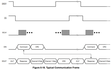
Also, please check the details in the session of 8.5.1.7 SPI Communication Frames in ADS131M02 datasheet. The following figure is a typical SPI timing for this ADC, you can monitor /DRDY signal or use that signal as an interrupt to your AM243x processor, the falling edge of /DRDY indicates that the data is ready to read, then you can send RREG, WREG command to read or write registers, or just send send out SCLK clocks by sending enough 0 data (NULL) to retrieve conversion data from the ADC via SPI interface.
In a weighing application, an ADS1235 (Analog-to-Digital Converter) and a 1022 load cell are used. However, at first, we have an ADC 15 click driver module itself ADS131M02 and we need to figure out how to collect data with that ADC in SPI interface, including ADC configuration, calibration, and filtering.
You prefer that link ads131m02 code is a MSP430 controller but we work with that AM243x launchpad
we still need your help on how to interpret the analogue data.
This is C code, it should be able to be used for other processor with some modifications. This is the only example code we have for ADS131M0x. As I said, you can also check the timing and the details in ADS131M02 datasheet, I can help you if you have any trouble to collect the data form the ADC.
The example code has a detailed description and explanation for each function and most code lines. I hope you can check the details first.
The function to read conversion data is "readData(adc_channel_data *DataStruct)" in ads131m0x.c file, you have to call this function in your main program. However, you have to check if the flag of "flag_nDRDY_INTERRUPT" is true in your main program loop before you call "readData(adc_channel_data *DataStruct)" function to read data. The flag of "flag_nDRDY_INTERRUPT" is set to "True" when the /DRDY signal triggers the interrupt and the "void GPIO_DRDY_IRQHandler()" interrupt routine is executed in hal.c file.
There is another alternative solution to read data, you can call "readData(adc_channel_data *DataStruct)" function in the "void GPIO_DRDY_IRQHandler()" interrupt routine in hal.c file instead of calling it in your main program loop.
I also strongly recommend you to check README file which has already shown how to use this example code step by step:
How to use this code:
----------------------------------
Reference the *ads131m0x.c* file while writing your own code for examples of how how to perform basic ADC operations, such as register read/writes and reading data...
OR
Copy and paste the example code into your project, and update the files as needed to get access to the provided APIs...
1. Copy the `ADS131M0x` and `HAL` module files into your firmware project.
2. Add library references in *hal.h* to your processor-specific library file(s).
3. Edit all of the function implementations inside of *hal.c* to provide the specified functionality with your processor and processor-specific library APIs.
4. Include a reference to *hal.h* somewhere in your program and call the **InitADC()** function to initialize the MCU peripherals connected to the ADC.
5. Include a reference to *ads131m0x.h* in your application (from *main.c* or wherever ADC communication is handled). You should now be able to begin calling the `ADS131M0x` module functions in your code.
Yes, I checked the flag of "flag_nDRDY_INTERRUPT" is true in the main programme loop when I use the "readData(adc_channel_data *DataStruct)" function to read data, however in that debugging session didn't go with that flag, it exited with that function.
Dale is out of the office right now, he will respond to later this week
However, if you have trouble with your serial communication, please send us clearly-labeled logic analyzer or scope shots of your communication so we can help diagnose issues.
uint8_t spiSendReceiveByte(const uint8_t dataTx)
{
    /*  --- INSERT YOUR CODE HERE ---
     *  This function should send and receive single bytes over the SPI.
     *  NOTE: This function does not control the /CS pin to allow for
     *  more programming flexibility.
     */

    // Remove any residual or old data from the receive FIFO
    uint32_t junk;
    while (SSIDataGetNonBlocking(SSI_BASE_ADDR, &junk));

    // SSI TX & RX
    uint8_t dataRx;
    MAP_SSIDataPut(SSI_BASE_ADDR, (uint32_t) dataTx);
    MAP_SSIDataGet(SSI_BASE_ADDR, (uint32_t *) &dataRx);

    return dataRx;
}
The preceding code has a msp430 driver library...How to rebuild this function in Am243x Launchpad?
If you have questions about porting code from one MCU to another, please post that question in the "Microcontrollers" forum and one of our experts will assist you
I am refer that AM243x MCU+ SDK example:mcspi_loopback_am243x-lp_r5fss0-0_nortos_ti-arm-clang. The McSPI instance initialization/open code is generated based on the example.syscfg by syscfg automatically. but I am using MCU_PLUS_SDK_AM243x_09.00.00.30, yet the mcspi driver source file only contains this mcspi transfer function (int32_t MCSPI_transfer(MCSPI_Handle handle, MCSPI_Transaction *transaction).
The SPI write and read functions are not provided...How to send the adc register and receive data?
bool readData(adc_channel_data *DataStruct)
{


    uint8_t dataRx[4] = {0};
    //uint8_t bytesPerWord = getWordByteLength();
    /* Set the nCS pin LOW */
    setCS(LOW);

    // Send NULL word, receive response word
    int i;
    dataRx[i] = spiSendReceiveByte(0xA5);

    DataStruct->response = combineBytes(dataRx[0], dataRx[1]);

       // Send 2nd word, receive channel 1 data
     dataRx[i] = spiSendReceiveByte(0x14);

     DataStruct->channel1 = signExtend(&dataRx[0]);

#if (CHANNEL_COUNT > 1)

    // Send 3rd word, receive channel 2 data

        dataRx[i] = spiSendReceiveByte(0x11);
        DataStruct->channel2 = signExtend(&dataRx[0]);


#endif

    /* Set the nCS pin HIGH */
    setCS(HIGH);

    // Returns true when a CRC error occurs
    return 0;
}


uint8_t spiSendReceiveByte( uint8_t dataTx)
{
  uint8_t dataRx;
  MCSPI_Transaction   spiTransaction;

  setCS(LOW);

       MCSPI_Transaction_init(&spiTransaction);
       spiTransaction.channel  = gConfigMcspi0ChCfg[0].chNum;
       spiTransaction.dataSize = 8;
       spiTransaction.csDisable = TRUE;
       spiTransaction.count    = (spiTransaction.dataSize/8);
       spiTransaction.txBuf    = (void *)dataTx;
       spiTransaction.rxBuf    = (void *)dataRx;
       spiTransaction.args     = NULL;

       DebugP_log("transmit data %d\r\n",dataTx);

       dataRx = MCSPI_transfer(gMcspiHandle[CONFIG_MCSPI0],&spiTransaction);
       DebugP_log("receive data %d\r\n",dataRx);


    setCS(HIGH);


    return dataRx;
}
In that preceding code is used in spi communication but that received data is 0. I need your help for solve that issue.
As Bryan has mentioned, you will ask the questions about MCU, you will have to post your questions to the Microcontrollers forum. If you want to debug the timing with ADC, please upload your timing plots including SCLK, DIN, DOUT, /CS and /DRDY which are captured with a scope or logic analyzer here, I can help you address the timing issue.