This thread has been locked.

If you have a related question, please click the "Ask a related question" button in the top right corner. The newly created question will be automatically linked to this question.

ADS127L21: ADS127L21 : What should I consider when using bipolar instead of unipolar?

Part Number: ADS127L21
Other Parts Discussed in Thread: THS4551, , PGA855, ADS127L11, THS4561
I am designing a circuit using THS4551(FDA) and ADS127L21(ADC).

Assuming you are using it in bipolar mode,

For THS4551
① Apply +2.5V -2.5V to VS+ and VS- respectively.

For ADS127L21
① AVDD1 = 2.5 V / AVSS = –2.5 V


I set it like this.

Regarding common mode voltage, is it okay to connect the ADS127l21's VCM terminal directly to the THS4551's VOCM terminal?

Probably VCM = VOCM = 0V.

One question is,

If you look at the THS4551's datasheet, it is written as VOCM = ((Vs+)-(Vs-))/2.

In this case, even if the THS4551's Vs+ = 2.5V / Vs-=-2.5V is applied,

So VOCM = (2.5 - (-2.5)) /2 = 2.5V?

Or does VOCM= (2.5 -2.5) /2 = 0V?

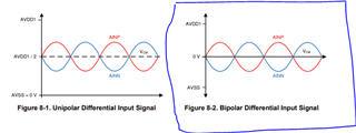
If ADS127L21 is set to Bipolar, VCM = 0V.

In this bipolar mode situation,

Is it a problem to connect the ADS127L21's VCM terminal directly to the THS4551's VOCM terminal? Isn't that a problem?

The data sheet is all explained in terms of Unipolar, which can be confusing.

I would appreciate your reply.

  • Hello Cheol,

     is it okay to connect the ADS127l21's VCM terminal directly to the THS4551's VOCM terminal?

    Yes, you can connect the L21 VCM terminal directly to the THS4551 VOCM pin.

    If you look at the THS4551's datasheet, it is written as VOCM = ((Vs+)-(Vs-))/2.

    This appears to be an error in the THS4551 datasheet and should read VOCM=((Vs+) + (Vs-))/2.  In other words, the default value of the VCOM pin will be the average, or midpoint, of the supply voltages.

    When using +/-2.5V supplies for the THS4551, the default output common mode voltage will be 0V, VOCM=(2.5+(-2.5))/2=0V, which is also the VCM output voltage of the ADS127L211 with AVDD1=2.5V and AVSS=-2.5V.

    In fact, since the ADS127L21 and THS4551 are both powered from the same power supplies, it is optional to connect the VCM and VOCM pins together, since they will both default to the same voltage.  This may make board routing a easier.

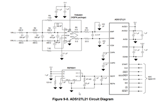
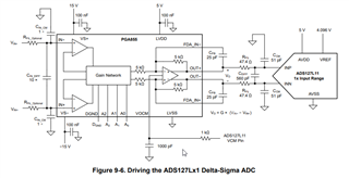
    This is shown in Figure 9-8 of the ADS127L21 datasheet.  Although this example uses a unipolar 5V supply for the THS4551 and ADS127L21, it also is valid using +/-2.5V supplies.

    Regards,
    Keith Nicholas
    Precision ADC Applications

  • Hi Keith,

    How should we configure the reference voltage at the ADS127L21 in +/-2.5 V bipolar application?

  • Hello Chia,

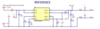
    I recommend powering the reference between AVDD and AVSS; this will allow reference voltages from 0.5V to 4.096V to be used.  This is also how the ADS127L21EVM is configured.

    Regards,
    Keith 

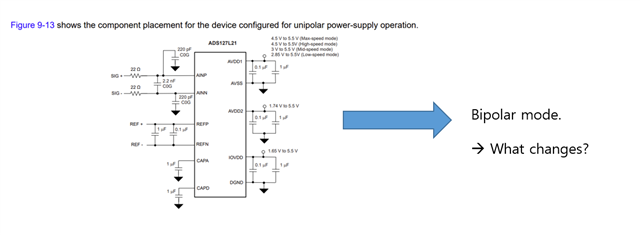
  • What changes when designing bipolar?

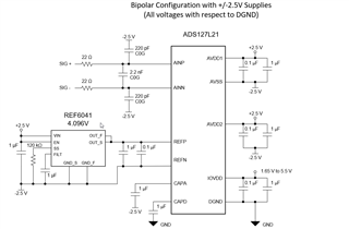
    There seems to be a point where something connected to GROUND needs to be changed to AVSS.

    I'm curious specifically how the circuit should be changed.

  • Hello Chia,

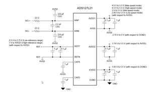
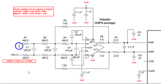
    Below is an updated drawing that shows what gets connected to GND and what gets connected to AVSS.

    When using +/-2.5V supplies, AVDD=+2.5V and AVSS=-2.5V, here are the specific connections.

    Regards,
    Keith

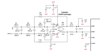
  • I am using ths4551 in front of adc127L21. In the case of bipolar, could you please let me know if there are any confusing factors in the ths4551 peripheral circuit?

  • We are designing a DAQ circuit.

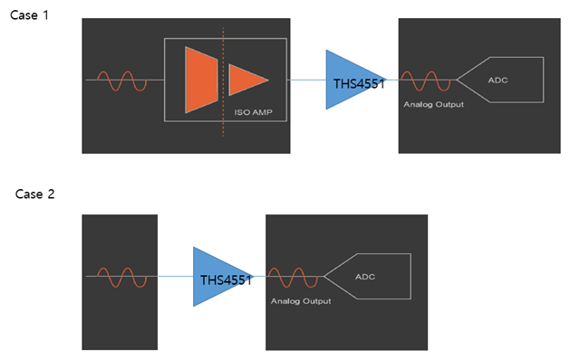
    The ads127l21 datasheet does not mention the isolation amp and is guided as case 2.

    Therefore, we would like to proceed with the design for case 2.

    However, I am curious as to whether it is necessary to design for case 1, or whether there will be no major problems in performing frequency analysis on the received data even if designed for case 2.

    (Use of designed DAQ: Acquire vibration data --> We plan to analyze frequency)

  • Hello Cheol,

    The THS4551 supplies should be powered from the same supplies as the ADS127L21.  In the case of bipolar supplies, Connect the AVSS to -2.5V and AVDD to +2.5V.  The below example shows how you can use the THS4551 to convert from a single-ended input to a differential output, and can support inputs of +/-4.096V.

    Normally for vibration sensors, isolation is not required and the sensors are DC coupled through the signal chain to the ADC.  What are your input requirements for the DAQ?  If you need multiple ranges and higher voltages (up to +/-15V), then you may want to use the PGA855 with the ADS127L21.

    Regards,
    Keith

  • I am so impressed by your kind explanation.

    As a customer who chose the ads127l21 device, I would like to ask you a question to resolve some questions.

    ① What are the advantages of designing with bipolar rather than unipolar? I don’t think there will be much difference in the results even if you design it unipolar instead of bipolar.


    ② We want to use 13.1072MHz for the adc oscillator and 16MHz for SCLK. The datasheet recommends integer multiples, but I understand it is not a requirement. Even if it is not an integer multiple, there is no big problem in receiving data, right? (There is a realistic reason why it must be designed this way in order to meet the SPS desired by the customer.)

    ③Basically, when configuring a circuit with a combination of THS4551 + ADS127L21, It is judged as a single-ended to differential signal method.

    Common sense suggests that most expensive DAQs use the differential to differential method. We would like to ask for an answer as to whether there will be any problem in signal measurement performance even if single-ended to differential signal is selected rather than sticking to the differential to differential method.


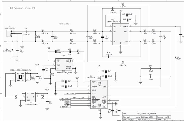
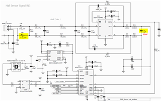
    ④ I drafted the circuit design as shown below. Are there any major problems if the design is completed like this?

  • Hello Cheol,

    I will review your latest questions by end of business tomorrow.

    Thanks,

    Keith

  • Hello Cheol,

    1.  Since you are using a fully differential amplifier to drive the ADC inputs, there is not really an advantage to use bipolar or unipolar supplies from a performance perspective.  Using bipolar supplies is advantageous when you want to precisely measure 0V in a single-ended signal chain.  Amplifiers operating from a unipolar supply (with the negative supply equal to ground) cannot output exactly 0V; there will always be a significant offset of mVs or 10's of mVs.  Operating the input signal chain at +/-2.5V supplies avoids this issue.  In this case, operating the ADC at these same supply voltages avoids additional needs to level shift the signal for the ADC when not using a fully differential amplifier as the ADC input driver.

    2.  In this case, I understand why you need to operate at a very specific data rate, however, it would be preferred to then use this frequency for the SPI SCLK frequency if possible.  If not, you will get mixing of the two oscillator frequencies which will show up in an FFT spectrum plot.  These spurs are usually small enough that SNR is only degraded by about 0.1dB, but will increase overall distortion of the acquired signal.

    3.  Differential signal chains have a couple of key advantages. However, depending on system level noise and the performance of the sensor, the overall differences may not be significant.

    (a)  Even order harmonics of the signal tend to be canceled out, leaving only odd order harmonics.  This improves the overall THD of the system.

    (b)  If the signal source has a different power supply and ground connections verses the DAQ unit, there can be common mode ground currents that can show up as differential noise in the measurement.  Using differential connections rejects a large amount of the common mode noise pickup, resulting in a lower distortion and lower noise acquired signal.  

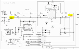
    4.  I reviewed your schematic and noticed two small corrections.  The input filter capacitor, C71, should be 2.2nF, not 2.2pF.  Since you are AC coupling the input signal, the negative input needs to also be AC coupled to ground.  This is necessary to maintain a proper common mode output level.

    Regards,
    Keith

  • 1-

    Since we use THS4551, there is no risk of output offset even if we use unipolar method, right?

    2 - 

    There may be an issue with the mixing of the two oscillator frequencies as you mentioned, but as long as the level is not very significant, we don't care.

    Isn't this causing significant distortion of the signal?

    According to current customer requirements, ADC's oscillator must use 13.1072MHz, and SCLK wants to use 16MHz Crystal. We also need to utilize daisy chaining to synchronize and receive multiple signals such as vibration, current, CAN signals, etc.

    (If we use 13.1072MHz SCLK as you said, we also need to synchronize and acquire CANFD data, and I understand that to process CAN data, we need to use an integer multiple of SCLK.)

  • Hello Cheol,

    1.  The THS4551 will set the correct common mode voltage using either unipolar or bipolar.  Using bipolar +/-2.5V supplies, the common mode will be 0V in this case, which is controlled by the ADS127L11 VCM voltage level.

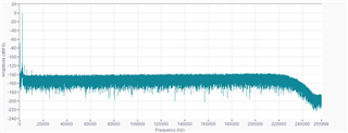
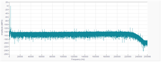
    2.  Below is a typical example using two different clocks.  It is not significant distortion and may be completely acceptable in your system.  I am not familiar with the CANFD requirements.

    Regards,
    Keith

    Spectrum using single clock source for both SCLK and CLK:

    Spectrum using two different clock sources for SCLK and CLK:

  • Thank you for your kind explanation. Thanks to this, my understanding of the elements has become clearer.

    I have one last question.

    Whether it is unipolar or bipolar, in the end it is just a method for power.
    This has nothing to do with the OFFSET of the signal. Right?


    For example, let's assume that an actual acceleration signal is input.
    Because the allowable signal range from +4.096 to -4.096 is determined based on the 4.096V reference voltage we applied,
    Even if we apply unipolar(+5V/0V) power, within the signal range (+/-4.096V), the AC signal can be acquired without OFFSET. right?

    In fact, I was confused about Power RANGE and signal RANGE depending on whether it was unipolar or bipolar.

    If I hear your answer to this, I think all my doubts will be resolved. thank you

  • Hello Cheol,

    Yes, the THS4551 takes care of all level shifting.  Using either +/-2.5V supplies, or a single +5V supply, you can connect one input of the THS4551 circuit (Gain=1) to Ground, and the other input can range from +4.096V to -4.096V when using a 4.096V reference.

    Regards,
    Keith

  • Thank you for your kind explanation. Lastly, I would like to ask you one more question ^^; T.T.

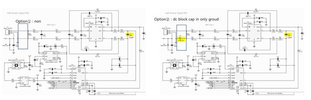
    Assuming that it is an input sensor that needs to measure both dc+ac, rather than measuring only ac signals, which is the better method, option 1 or option 2?

  • Hello Cheol,

    Only option 1 will work to measure DC signals or DC+AC signals.  Option 2, as drawn, will not work correctly for any combination.

    If you want to only measure AC signals, then you can AC couple using a capacitor in both the signal input and ground path, as suggested earlier and shown again below.

    Regards,
    Keith

  • In the case of Ths4551, the voltage range is only 5V, so we plan to change the design to Ths4561 in the future.

    In that case, I think there is an advantage in being able to take the voltage range of +-5V, that is, 10V.

    If we apply +5V and -5V to the voltage of ths4561, I wonder if the voltage of ads127L21 must also be set to bipolar or if it is okay to set it to unipolar.

    I think that to set Vocm and VCM to be the same, ADS127L21 should also be set to Bipolar.

    Am I right?

  • Hello Cheol,

    The THS4561 will correctly adjust the output common mode to the level needed by the ADS127L21 since the VCM output of the ADS127L21 is connected to the VCOM input of the THS4561.  If the ADS127L21 is powered from +/-2.5V supplies, then the common mode will be 0V.  If the ADS127L21 is powered from +5V single supply, then the common mode will be +2.5V; either configuration will work.

    However, I would advise to always use the same power supplies for the input amplifier as the ADS127L21.  Using +/-5V supplies for the THS4561 could result in the ADS127L21 inputs exceeding the ABS max input voltage during some sort of over-range event.  As long as the THS4561 uses the same supply voltages, then the outputs of the amplifier will never exceed the input voltage ratings of the ADS127L21.  Since the input to the THS4561 is through a resistor network, any input over-voltages at the THS4561 inputs will be attenuated by the resistor network.

    The THS4561 provides very similar performance as the THS4551 when driving the ADS127L21, but uses about 1/2 the supply current, making the THS4561 a good lower power alternative to the THS4551.  As you noted, it can operate from higher supply voltages (+/-5V), but this is not an advantage when used as the input driver for the ADS127L21.

    Regards,
    Keith