Other Parts Discussed in Thread: AFE881H1
Hi,
I am trying to send data from my micro to HART modem device mentioned above.
Steps performed are
Set the threshold value to 3 which means after 6 levels in the FIFO of data IRQ will get generated
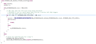
Write the data in to the FIFO U2H (HART is already enabled in the configurations) FIFO written up to 32 levels
RTS assert
wait for CTS assert
after this AFE882H1 will automatically start to send data to the MOD_OUT pin right as the data is already in the FIFO
once the IRQ comes (if the FIFO has reached to level 6) again keep enqueuing data until complete HART frame is completed.
I have 1 question here
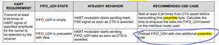
Firstly its recommended to send the preamble bytes right so out of 32 levels 1 level is preamble byte right is I want to send 2 preamble bytes and 10 bytes of data (all 0's)
what is the sequence ?
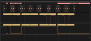
0x15(fifo reg wr ) 0x01 (parity) Data (0xFF preamble) now shall i keep writing data and FIFO pointers will increment on its own like
0x15(fifo reg wr ) 0x01 (parity) Data (0xFF preamble) (Data (0xFF 2nd preamble byte) Data (0x00 actual data) Data (0x00 actual data) Data (0x00 actual data) likewise
or for every byte need to send
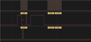
0x15(fifo reg wr ) 0x01 (parity) Data (0xFF preamble)
0x15(fifo reg wr ) 0x01 (parity) Data (0xFF 2nd preamble byte)
0x15(fifo reg wr ) 0x01 (parity) Data(0x00 actual data)
0x15(fifo reg wr ) 0x01 (parity) Data(0x00 actual data) till 10 bytes transferred
Thanks,
Aarti