This thread has been locked.

If you have a related question, please click the "Ask a related question" button in the top right corner. The newly created question will be automatically linked to this question.

ADS1263: IDAC calibration returning unexpected value

Part Number: ADS1263

Hi Team

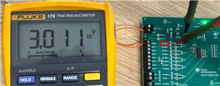
Since the ADS1263 IDAC has a wide tolerance (max ±4%) we are using an external resistor to calibrate it. For example, we set IDAC1 to output 1mA, put this through a 1K calibration resistor (R8 below) and read back ~1V as expected. 

The issue we are seeing is that when we set IDAC1 to 3mA, we only see ~2.5V across the 1K calibration resistor... instead of the expected ~3V. 

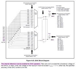
Digging through the datasheet I see comments like below. Does this mean max IDAC current is actually limited by the internal 2.5V reference, and if we want to calibrate at 3mA then we need to reduce the calibration resistor to <833R (2.5V / 3mA)? Or have we made a silly mistake in our ADC configuration/conversion? 

Cheers, Anton

  • Hi Anton Ivanovsky,

    I tried this on the ADS1263EVM and got the results shown below. I tied AIN0 to ground and then measured across the filter resistor (R5) that is 1kohm. I then measured 3V between the resistor and ground.

    When you say that "read back ~1V as expected", are you using the ADC for this measurement or a DMM as I did? If you are using the ADC, what reference source are you using for the measurements? If you are using the internal reference, then the measured differential input can only be +/-2.5V

    -Bryan

  • Hi Bryan

    Thanks for getting back to me so quickly. 

    We are reading the voltage with the ADC instead of a DMM. For IDAC calibration we are using the internal 2.5V reference, so that explains the 2.5V "limit" when reading the voltage degenerated with 3mA across a 1K resistor. Do you know if it's possible to configure the ADC to use an external 5V reference for IDAC calibration? Currently we have this 5V reference connected to AIN0 (+5VREF) & AIN1 (GND).

    Reason for asking is that the highlighted datasheet comments in my original post make it seem like we are limited to the internal 2.5V reference?

    Cheers, Anton

  • Hi Anton Ivanovsky,

    The ADC can measure within its full-scale range, which for the ADS1263 is FSR = +/-Vref / gain. So if you are using the internal VREF and gain = 1, then FSR = +/-2.5 / 1 = +/-2.5V. Therefore, the differential voltage (AINP - AINN) must be within this range.

    To calibrate your IDAC, you will need to enable the internal VREF in order to use the IDAC, but you will have to select a larger reference voltage as your reference source. If you already have +5V between AIN0 and AIN1, then you can select these inputs accordingly as shown in the image below. Now you should be able to read voltages >2.5V with the ADC

    -Bryan

  • Thanks Bryan, that solved the issue :D

  • Hi Anton Ivanovsky,

    I am glad we could help resolve your issue

    -Bryan