This thread has been locked.

If you have a related question, please click the "Ask a related question" button in the top right corner. The newly created question will be automatically linked to this question.

ADS124S08: 3-Wire RTD

Part Number: ADS124S08


Dear Technical Support Team,

I'd like to measure 2cases range of temperature with 3-Wire RTD for PT100.

①0℃~150℃  ⇒ 100Ω~157.33Ω

②0~400℃  ⇒ 100~247.09Ω(Expand from ①157.33Ω to 247.09Ω)

Q1

Is it necessary to change settings (gain, etc.) according to the range of resistance change?
I would like to know the settings to prevent accuracy deterioration due to an increase in the measurement range from ① to ②.

Q2

If the measurement resistance change range 100 to 157.33Ω is expanded to 100 to 247.09Ω, is it necessary to change the input circuit constants, etc.?
I would like to know the settings to prevent accuracy deterioration due to an increase in the measurement range from ① to ②.

My 3-Wire RTD HW configuration is copied from EVM.

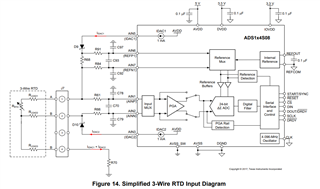
■Following is my understanding.

ADS1x4S08 Evaluation Module(SBAU272A) page 21 shows following formula.

RRTD = (2 × R68 × ResultCODES / PGA ) / (2^24 – 1)

RREF=R68=1kΩ、PGA=4、Code=FullScale=7FFFFF(HEX)

Then max measurement range of RRTD is 250Ω. 

It can cover the range of ① and ②, and it seems the best configuration to measure the range of ① and ②.

However if you have the best configuration for each ① and ②, please let me know.

R68 1000 Ω
ResultCODES 8388607(DEC) 7FFFFF(HEX)
PGA
RRTD 250 Ω

Best Regards,

ttd

  • Hi ttd,

    The EVM shows one possible example of how to connect an RTD for measurement using a high-side reference.  It was designed in such a way to measure 2-wire, 3-wire or 4-wire RTDs.  If the application  uses a 3-wire RTD only, the configuration of the EVM may not be the best choice.  I would suggest reviewing the various 3-wire design configurations given in A Basic Guide to RTD Measurements.  The guide will help you with your understanding of the RTD configuration and design process.

    There is also another design tool which is useful so that you can optimize the design once you decide on a configuration.  This downloadable tool is the ADC-RTD-CONFIG-CALC .

    Best regards,

    Bob B

  • Hi Bob,

    Thank you for your reply.

    I have question about ADC-RTD-CONFIG-CALC .

    R_PROTECT, R_MISC_H, and R_MISC_L are for protection in case of short circuit, etc,

    In an actual circuit, a 1k or several k resistor should be inserted.
    Is it correct understanding?

    EVM seems not to have these register, I set 0Ω for calculation.

    Best Regards,

    ttd

  • Hi ttd,

    There is a note in the calculator at the bottom of the different configurations that states:

    So on the EVM these R_PROTECT, R_MISC_H, and R_MISC_L resistors are not used as the measurement is high-side on the EVM and uses a diode to limit the current into the IDAC pins.  You can use resistors instead.  The values you would use depends on any expected overvoltage condition where the resistors will limit the current into the device pins (10mA or less), but also must be small enough so as to maintain the IDAC compliance voltage for the total current path.

    Best regards,

    Bob B