This thread has been locked.

If you have a related question, please click the "Ask a related question" button in the top right corner. The newly created question will be automatically linked to this question.

DAC5675: Termination of differential signal on clock inputs

Part Number: DAC5675

Hey,

I am working with balun design that will convert single ended 50Ohm RF line to differential input for the DAC. Looking in the datasheet (Figure 1. Application Schematic)  I see that there is a 200 ohm termination of diff. line suggested coming after 1:4 balun. Does that suggest that the differential line between the balun and the DAC should have 200 ohm diff. characteristic impedance?

In RF context, when I hear about a transition from unbalanced to balanced it is usually 50 Ohm on the single-ended side transitioning to 100 Ohm on the differential side.

Is it maybe so that the differential line impedance depends on the balun ratio? Ie if for 1:4 the suggestion is 200Ohm, would a suggestion for 1:2 balun be 100Ohm?

Thanks!
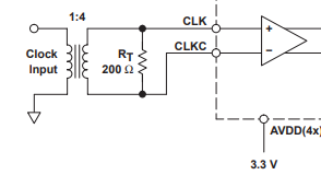
  • Hi Ivan,

    If the single ended input is 50 ohm, and passes through a 1:4 balun, the differential output resistance of the balun will be 5*4=200ohm. The 200ohm resistor is in parallel with the balun output, which makes two 200ohm resistors in parallel or a single 100ohm equivalent resistance. If you can find a 1:2 balun which fits the bandwidth requirements for your system then no additional resistor is necessary.

    Thanks, Chase

  • Ok, so if I understand correctly, the output resistance of the balun in parallel with whatever resistance has to equate to 100 Ohm in order to terminate the differential line. In other words, the differential charactersitic impedance of the pair is 100ohm and in order to terminate it you need 200Ohm because output resistance of the balun is 200Ohm. (which in parallel give 100ohm)

  • Ivan,

    Yes, it is a parallel resistor.

    Thanks, Chase

  • Does this still apply if I have a long differential pair between the DAC and the output of the balun?

    In other words, it sounds unusual to me to terminate the diff. pair with a resistor on the end connected to DAC in parallel with the end connected to balun output...and in between I have a long diff. pair. Would I need some other value in that case?

    Thanks!

  • Hi Ivan,

    In this case, after the parallel 200 ohm resistor which sets the differential line at 100ohm, you should place 0.1uF series capacitors to AC couple. This will isolate and allow a 100 ohm termination close to the DAC clock input as well which leaves the transmission lines both at 100 ohm on each side of the capacitors.

    Thanks, Chase