This thread has been locked.

If you have a related question, please click the "Ask a related question" button in the top right corner. The newly created question will be automatically linked to this question.

ADC3244: ADC3244 with INA851 frontend, possible damage to adc inputs?

Part Number: ADC3244
Other Parts Discussed in Thread: INA851, ADS127L11, ADS127L21

Good morning,

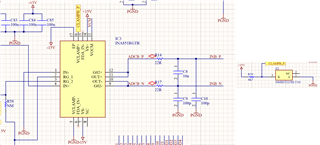
I had problem with ADC3244 which became obvious when measuring from 16 of them at the same time. There is large mismatch between values which they return. Frontend is made from high-pass filter and INA851 differential amp connected to ADC input via resistors and low pass filter according to documentation. Clamp - pin is connected to ground, clamp + to zener diode stabilised reference. Important information is that INA is powered from symmetrical +/- 15V supply.

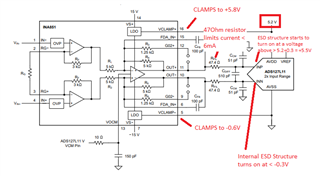
Recently investigation showed that when input of INA is overloaded output swings 0,5V below ground. That situation can lead to damage in practice? I tested many chips, it looks like that transients lead to damage but i wonder how to mitigate it without concerning bandwidth and signal quality. Damage mode if IC's were mostly measuring off values or lack of output clocks.

  • UPDATE:

    I've added diode with pullup resistor to +15V rail for clamp- pin. It resolved this situation and now output voltage is reaching 0V instead of negative 0,5V. Nevertheless i am still curious if negative swing can result in such strange failure mode.

  • Hi Tomasz,

    Can you please provide a schematic and/or block diagram on your circuit implementation? This would be more helpful to follow.

    Thanks,

    Rob

  • Unfornately schematic symbols are not very clear but it should do the job. INB_P and INB_N nets are connected directly to ADC input as well VCM is connected with decoupling caps to pin 24 of ADC3244 

  • Hi Tomasz, 

    I am reaching out to our amplifier team to help. Please give me a fews more days to respond.

    In the meantime, it would be best to send a more complete schematic of the INA, particularly a snippet that shows how the inputs of the INA are connected too.

    Basically what I see happening is you have a mismatch in the output common mode of the INA connected to the ADC, VCM = +0.95VDC. Therefore, there is an imbalance, possibly on the inputs of the INA, forcing the INA outputs to rail from one compliance range to the other since the INA has a large supply range, ie - +/-15V.

    Clamping the outputs will help and keep the signal within range of the ADC's input swing and compliance range, 2Vpp DIFF.

    Regards,

    Rob

  • Hi Tomasz,

    The INA851 output CLAMP+ and CLAMP- function of the INA851 is explained on page 28 of the INA851 data sheet.  The INA851 clamp function may not be compatible with the ADC3244 due to the small ADC voltage supply requirement of 1.8V.  Please see detailed explanation below.

    In essence, the clamp pin allows the output of the INA851 to swing to the complete VCLAMP+/VCLAMP- voltage without distortion; and as you have confirmed on your bench set up, the CLAMP function only starts to turn on at an output voltage 500mV beyond the CLAMP+ and CLAMP- voltage.  Hence, when the clamping function is in use, the output voltage is clamped (completely turned on) at approximately 600 mV beyond the clamp voltage.  In your case, the INA851 output will clamp hard at -600mV below CLAMP- (GND) and +600mV above the ADC positive supply.  In addition, for the output driver to function correctly, the CLAMP+ and CLAMP- require to be more than 3 volts apart. 

    Please see section 8.3.5 p.29 (also below) from INA851 data sheet for detailed description:


    The INA851 is often used to drive high-resolution precision SAR ADCs that support sampling rates around 1-MSPS, and precision Delta-Sigma ADCs that produce output data rates in the 1365 kSPS.  On most precision ADCs, on a fault, the ADC inputs can tolerate an input current of ±10mA when the input voltage exceeds the supply voltage. This could (need to confirm?) be different for the ADC3244.

    For example, on the ADS127L11 circuit below, per the ADS127L11 data sheet Absolute Maximum Ratings, the device can tolerate an input voltage of AVSS-0.3V to AVDD1+0.3V. If the absolute maximum voltage is exceeded, the ADS127L11 input current must be limited to less than ±10mA.

    In the ADS127L21 circuit example below, the recommended R-C-R filter is 47Ω+560pF+47Ω.  This filter is carefully tuned/selected while accounting for INA851 stability, settling and AC performance, and also, to limit the current at the inputs during a fault. The internal ADC ESD structure in the ADS127L11 case starts to turn-on at voltage 0.3V above the +5.2V supply (in reality, the ESD structure starts to turn on around 0.5V at room temp, so this estimate is conservative), and the INA851 clamps at 0.6V above the supply (+5.8V), the current through the 47 Ω resistor is only (5.8V-5.5V)/47Ohm = ±6.4mA, which is safe for the ADS127L11:


    However, in the ADC3244 case:

    • The ADC3244 requires an analog supply of +1.8V, which unfortunately, violates the INA851 minimum clamp voltage specification. See CLAMP+ and VCLAMP- minimum voltage requirement:
    • The INA851 VOCM pin requires a headroom of 1.5 minimum below VCLAMP+ and above VCLAMP-. This is not compatible with the ADC3244 that uses a 1.8V voltage supply.
    • The R-C-R resistor filter chosen with the 22Ω series resistor may not be sufficient to limit current. You could adjust and increase the series filter resistors and reduce the filter differential capacitor, keeping the same time constant, while reducing the input current.
    • The ADC3244 ESD cell may (or may not?) be rated to withstand the ±10mA current when the absolute max voltage is exceeded. This may be different than the precision ADCs above. I would need to confirm with the ADC team this specification.

     In summary, the INA851 clamp function may not be compatible with the ADC3244 due to the small supply voltage requirement of 1.8V.

    Thank you and Best Regards,

    Luis

  • HI Tomasz,

    Corrected the ADC part number to ADC3244 on the discussion above.

    Thank you and Regards,

    Luis