This thread has been locked.

If you have a related question, please click the "Ask a related question" button in the top right corner. The newly created question will be automatically linked to this question.

ADS114S08B: START/SYNC - pin statement in the Datasheet

Part Number: ADS114S08B

Hello everyone,

me and my team have been working on a design incroporating the mentioned chip. After completion of the desing phase of this project, we discovered in the datasheet the following statement:

Tie the START/SYNC pin low when the device is controlled through the START and STOP commands. The START command is not decoded if the START/SYNC pin is high.

We sadly missed the statement that the Pin has to be tied to GND when using SPI commands only and therefore left the pin floating. With all of our 4 Prototype iterations we never encountered any issues, which is why we never noticed until now.

We are now in the QC of the series production units and are facing the issue, that some ADCs do not start reading any values or transmitting them over SPI after first bootup.

It seemed like the design flaw stated above would most certainly be the cause of this problem, which is why we ran some tests with the pin actively pulled high to reproduce this randomly appearing behavior. Contrary to our expectations, the conversion could successfully be started several times after bootup with the START/SYNC pin directly tied to the 3V3 (IOVDD) rail. This, to my understanding is contradictory to the information stated in the datasheet where it is stated that The START command is not decoded if the START/SYNC pin is high. I would kindly ask you to clarify how this could be possible? Am I missing something here or is the statement from the datasheet incorrect?

In addition to that, there is a flowchart showing the operating Modes of the ADC on page:

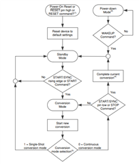
This suggests, that the START/SYNC- pin has to be actively pulled up again after starting the continuous conversion (where it has to be low for the start command to be registered). Otherwise it would "exit" the continuous conversion loop and to back to standby mode. I cannot believe this is how it is intended, because that would make the option to use only the SPI commands pointless, as you would have to actively control the START/SYNC pin anyways. Can you please clarify this too?

We have the option to manually solder the START/SYNC pin to a close by ground copper pour, but only want to do so, if we know that this solves our issues of temporarily not receiving any data from the adc, as would involve quite a bit of rework as you may understand. Therefore we have to be really certain, why I am seeking help in this forum. 

Any help would be very much appreciated.

Thank you,

David

  • Hi David,

    Welcome to the E2E forum! I can certainly see why this may be confusing.  The pin setting is meant to override the function of the SPI commands by design.  The state machine within the ADC will get confused unless there is a control that has priority and in this case it is the pin.  For example, let's say you are operating in continuous mode and set the pin high which will start conversions.  If I were to send the STOP command to stop conversions the pin is still high meaning I want conversions to take place.  So this is contradictory and the digital designer decided to make the pin the priority when set high.

    In addition, the START/SYNC pin can be used to synchronize multiple devices within a system so that the conversion starts (or restarts) within a couple of modulator clocks of the same time between devices.  This becomes a little more cumbersome using SPI commands when multiple devices are connected.

    As far as the reconciling the flowchart to the actions within the device, there are actually two modes of operation (single-shot and continuous) and the pin action responds slightly different depending on the mode.  For the pin, any rising edge will start a conversion.  In single-shot mode the conversion will start requiring a low to high transition to start the next conversion.  If in continuous mode the first rising edge of START/SYNC will start the first conversion and the conversion will continue until the START/SYNC pin goes low.  The actions of the SPI command requires that the START/SYNC pin be held low.  In single-shot mode, the conversion begins following the decode of the START command and requires another START command to begin the next conversion.  In continuous mode, the START command is required to begin conversions and to STOP conversions the STOP command is issued.  As a side note, to restart a conversion by command requires that the STOP command be sent followed by the START command.  Just sending the START command alone will not restart a conversion already in progress.  Perhaps with this additional information the flowchart will make more sense.

    As to the conversions starting following power-up with the START/SYNC pin pulled high, this would be the expected operation as the default mode is continuous.  It may also be possible that the START command may work in single-shot mode with the START/SYNC pin pulled high, but I have never tried it.  At any rate it is easiest to explain without adding too many conditions (there are enough already to make this confusing).  If you are using commands pull the START/SYNC pin low.

    The last point I wish to make is you should never let the digital input pin float.  The reason is the pin could float to any value, and if CMOS pins are at mid-IO supply both the NMOS and PMOS will be in conduction and power consumption can be quite high.  As the pin takes priority, a float condition could be problematic as the state of the pin can fluctuate to either high or low and be influenced by external noise entering the pin.

    Best regards,

    Bob B

  • Hello Bob,

    thanks for your quick and thorough reply :) Although generally you have answered all of my initial questions I'd still like to follow up on some things to make sure I understood you correctly. Just for clarification in advance - we are indeed running the ADC in continuous conversion mode, not in single shot mode. I will be referring to the START/SYNC pin as "Pin" in the following questions.

    If I understood the part about the Pin overriding the SPI commands correctly, the following would be the consequence (for continuous conversion):

    1. When the Pin gets pulled up for some reason (i.e. noise entering the pin) the conversions will be initiated regardless of wether the start command has been sent or not
      1. If the pin stays in high state, the conversions continue indefinetely 
      2. If the pin goes low, the conversions stop until there is a start command again

    Could it be, that scenario b. was the one, causing the ADC not to transmit any converted Data over SPI after startup? Meaning that during powerup the Pin was pulled up due to noise and then went back to low state, therefore starting up and then stopping the conversions again. But as we had already sent the start cmd at that time, the conversion never started again, showing only zeros as measurement.
    If so, would the values not just stay the same from the last conversion or are they reset to zero once there are no more conversions taking place?

    The reason I am asking this is not to see wether we should leave the pin floating after all (this is clearly not an Option, I can see that now) but to understand wether we still have a different issue undiscovered, maybe on the software side. If we could verify that the floating Pin was causing this issue then we dont have to look for another source of the problem.

    Also, with regards to the flowchart - I understand now, that the "OR" in the "START/SYNC pin low or STOP Command?"-Bracket for continuous conversion is not a logic "OR" but reflects two different scenarios. When the conversion is started by the rising edge of the Pin, the stop condition is the low state of the Pin. If the conversion is started with an START SPI command, the stop condition is the STOP- SPI-command, as the START/SYNC Pin has been low before anyways. 
    To me, that would be way less confusing when those wouldve been just two different charts - one for triggering with the pin and one for triggering with SPI commands, but oh well. At least now I understood.

    Thanks in advance for your further answers,

    David

  • Hello Bob,

    since my response from earlier we have been testing around to see how the adc really behaves with different sequences of pulling start/sync pin high or low and sending start/stop commands via SPI and we have come to the following conclusions:

    The stop command has to be of the same kind as the original start command, meaning that

    • If the continuous conversion start is issued by the rising edge on the start/sync pin, it can only be stopped by a falling edge on the start/sync pin
    • If the continuous conversion start is issued by the start command over the SPI interface, it can only be stopped by a stop command over the SPI interface and NOT BY PULLING START/SYNC LOW.

    maybe to you this was obvious, but to us it was not.
    This suggests, that the cause for the ADC not transmitting any data seems to be the following - After startup, due to noise the start/sync pin is pulled high, causing the start of continuous conversion to be triggered. The start command is sent via the SPI interface during the already running continuous conversion and therefore not decoded. After that, the pin goes low causing the continuous conversion to stop. Because the initial start command via SPI has already been issued the conversion is not starting up again.
    As there is no direct way of detecting that the conversion has been stopped it can also not directly be initiated afterwards via SPI, leaving us no other choice than to solder the pin to GND.

    Would you agree with those conclusions?

    Greetings,

    David

  • Hi David,

    It is difficult to say with any precision what actually has taken place.  It does seem to be a reasonable theory.  I agree with bullet point 1, but not sure how you would actually determine bullet point 2.  The bottom line is to not mix the two methods together.  Either just use the pin or just use the commands (with the pin held low).  I think it is best stated in section 9.4.4 of the datasheet in the second to the last paragraph where it states "If using commands to control conversions, keep the START/SYNC pin low to avoid possible contentions between the START/SYNC pin and commands."

    One additional comment I wish to make is when changing certain mux values (as mentioned in section 9.5.3.12 in the datasheet) or using a pulse on the pin or issuing a STOP/START command sequence, the digital filter will be reset and a new conversion will be initiated.  When this takes place the conversion data will change to '0' until a new conversion has completed.  In the mux discussion when using continuous conversions it is stated "When the device is configured with WREG, the first data ready indication occurs after the new conversion completes with the configuration settings. The previous conversion data are cleared at restart; therefore read the previous data before the register write operation."  So keep in mind that depending on order of operations and when the conversion data are read you may see the result as '0' until the conversion has completed.

    Best regards,

    Bob B

  • Hello Bob,

    Thanks for you help once more.
    Since our last contact we have been manually soldering the START/SYNC pins to Ground, following your advice.

    Now we restarted our Quality control procedure and sadly had to notice, that the issue remains. After booting up the board, the ADC does not read any values. Sending the stop command followed by a start command via SPI showed no effect. Only once we sent the reset Command via SPI, the ADC started conversion again. 

    Any suggestions what may cause this issue?

    Greetings,

    David

  • Hi David,

    I reread the initial post again and I missed the point "after first bootup".  Connecting the START/SYNC pin to ground is the correct procedure, but I guess we need to find the 'real' issue.  It would be helpful to see your schematic (you can start a private conversation with me by clicking on my name and attaching it to the conversation), and it would be helpful to know the entire ADS114S08B configuration settings.  Scope or logic analyzer shots of the communication would also be helpful.

    To talk to the device requires that all supplies are at nominal operating voltages (AVDD, DVDD and IOVDD) and the RESET pin pulled high.  It is also helpful to wait until the device has completely started (a minimum of 2.2ms) before attempting to start conversions or configuring the device.

    We have seen where customers try to communicate to the device too early or perhaps apply power where a sensor is powered slightly before the ADS114S08B which can place the analog in an odd operating state.  In this case you would need to either hold off setting the RESET pin high until the system voltages settle (which assumes you have control over the RESET pin) or issue the RESET command.  Section 10.1.6 in the datasheet shows a pseudo code example for startup.  This code example shows a startup process flow with some included 'optional' items where one is the sending of the RESET command.  Follow this process flow and add the RESET command and see if you can get the desired result.

    Best regards,

    Bob B

  • Hi Bob,

    Thanks for your thorough reply. Issuing the RESET command in the init routine seems to have solved our issue.

    However, in the meantime we have encountered a different problem:
    We are using a RC-filter at the input of the ADC and somehow the voltage at the ADC pin in some instances is not the same as on the other side of the resistor of the RC-filter. Instead of 0V we are measuring 0,66V at the ADC input pin.

    I had the suspicion that this was due to either the VBIAS, the IDACs or the BOCSs. But after checking the register values, sadly none of the above functions is the source of our problem, as they are all are in default (deactivated) state. 

    Do you have any other idea, what could cause this or what I might have overlooked?

    Greetings,

    David

  • Hi David,

    I don't have enough information here.  Can you give me your schematic and register configurations that you are using?

    Best regards,

    Bob B