This thread has been locked.

If you have a related question, please click the "Ask a related question" button in the top right corner. The newly created question will be automatically linked to this question.

DATACONVERTERPRO-SW: dynamic configuration window description

Part Number: DATACONVERTERPRO-SW
Other Parts Discussed in Thread: AFE7900EVM, TSW14J57EVM, AFE7900

Hi,

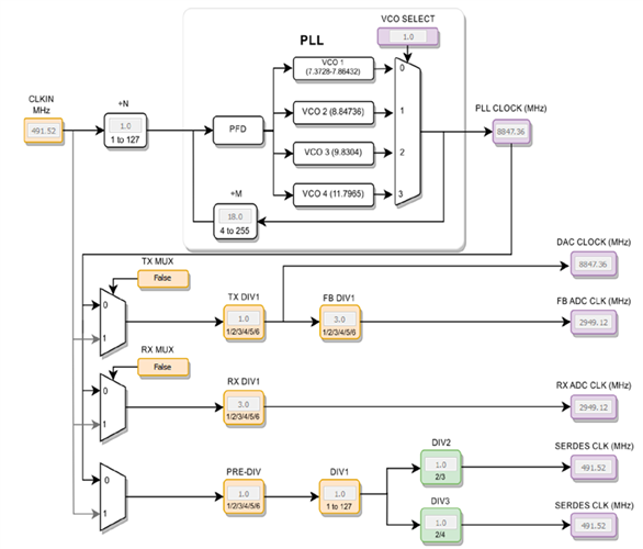
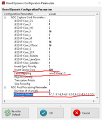
i'm trying to make small changes to one of TI's for AFE7900EVM standard configs and am running into a problem: the dynamic configuration window is not described in HSDC Pro User Guide, and when i'm trying to logically change some values, the TSW14J57EVM board starts to not capture data correctly and requires a firmware reboot. Please describe to me the parameters marked in attached screenshot so that i can achieve desired configuration.


Regards,

Oleg

  • Hi Oleg,

    Please see the manual below for descriptions of the parameters.

    TSW14J57 DAC INI File Guide.doc

    We could also provide you with .ini files if you can give us the AFE7900 bring up file you intent to use.

    Best,

    Camilo

  • Hi Camilo,

    Thanks for your reply. Looking through the guide you attached, i think bringup must be a problem. Im trying to collect data only from one channel, but when i disable all channels except the RxC channel, in AFE iGUI in JESD TX tab all JESD lines become inactive. Here's my bringup code with some changes for new lmk configuration

    ##############		Read me			##############
    #In HSDC Pro ADC tab, Select AFE79xx_2x2RX_24410; Data Rate = 245.76M ---> To capture 4 RX channels
    #In HSDC Pro ADC tab, Select AFE79xx_1x2FB_44210; Data Rate = 491.52M ---> To capture 2 FB channels
    
    sysParams=AFE.systemParams
    sysParams.__init__();sysParams.chipVersion=chipVersion
    
    setupParams.skipFpga = 1 # setup FPGA (TSW14J56) using HSDC Pro 
    
    ##############		Top Level			##############
    sysParams.FRef			= 256 #491.52
    sysParams.FadcRx		= 3072
    sysParams.FadcFb		= 3072
    sysParams.Fdac			= 3072*3
    sysParams.externalClockRx=False
    sysParams.externalClockTx=False
    													
    ##############		Digital Chain		##############
    
    		#####	RX	#####
    sysParams.rxEnable = [True,True,True,True]
    sysParams.ddcFactorRx	=	[32]*4			#DDC decimation factor for RX A, B, C and D
    ##sysParams.numRxNCO		=	2
    sysParams.rxNco0		= 	[[3700,5400],			#Band0, Band1 for RXA 
    							[1000,2000],        	#Band0, Band1 for RXB 
    							[1518,1542],        	#Band0, Band1 for RXC 
    							[1518,1542]]        	#Band0, Band1 for RXD
    ##sysParams.numBandsRx 	= 	[1,1,1,1]
    ##sysParams.rxNco1		= 	[[5400,5400],			#Band0, Band1 for RXA 
    ##							[1643.5,1643.5],       	#Band0, Band1 for RXB 
    ##							[2500,2500],        	#Band0, Band1 for RXC 
    ##							[1800,1800]]        	#Band0, Band1 for RXD
    
    		#####	FB	#####
    sysParams.fbEnable = [False,False]
    sysParams.ddcFactorFb	=	[12,12]					#DDC decimation factor for FB 1 and 2
    sysParams.fbNco0		= 	[500,1800]				#Band0 for FB1 and FB2 
    
    		#####	TX	#####
    sysParams.txEnable = [False,False,False,False]
    sysParams.ducFactorTx	=	[18,18,18,18]			#DDC decimation factor for TX A, B, C and D
    sysParams.txNco0		= 	[[5400,5400],			#Band0, Band1 for TXA 
    							[500,500],        	#Band0, Band1 for TXB 
    							[2500,2500],        	#Band0, Band1 for TXC 
    							[1800,1800]]        	#Band0, Band1 for TXD 
    
    
    ##############		JESD		##############
    
    		#####	ADC-JESD	#####
    sysParams.jesdSystemMode= [3,3]
    													#SystemMode 0:	2R1F-FDD						; rx1-rx2-fb -fb
    													#SystemMode 1:	1R1F-FDD						; rx -rx -fb -fb
    													#SystemMode 2:	2R-FDD							; rx1-rx1-rx2-rx2
    													#SystemMode 3:	1R								; rx -rx -rx -rx
    													#SystemMode 4:	1F								; fb -fb- fb -fb
    													#SystemMode 5:	1R1F-TDD						; rx/fb-rx/fb-rx/fb-rx/fb
    													
    sysParams.jesdTxProtocol= [0,0]						# 0 - 8b/10b encoding; 2 - 64b/66b encoding 
    sysParams.LMFSHdRx		= ["12410"]*4
    													# The 2nd and 4th are valid only for jesdSystemMode values in (0,2).
    													# For other modes, select 4 converter modes for 1st and 3rd.
    ##sysParams.LMFSHdFb		= ["12410","12410"]
    
    sysParams.rxJesdTxScr	= [True,True,True,True]
    sysParams.fbJesdTxScr	= [True,True]
    
    sysParams.rxJesdTxK		= [16,16,16,16]
    sysParams.fbJesdTxK		= [16,16]
    
    sysParams.rxDataMux		= [0,1,2,3,4,5,6,7]
    sysParams.jesdTxLaneMux	= [0,1,2,3,4,5,6,7]			# Enter which lanes you want in each location. 
    													# For example, if you want to exchange the first two lines of each 2T,
    													#		this should be [[1,0,2,3],[5,4,6,7]]
    
    		#####	DAC-JESD	#####
    sysParams.jesdRxProtocol= [0,0]
    sysParams.LMFSHdTx		= ["44210","44210","44210","44210"]
    sysParams.jesdRxLaneMux	= [0,1,2,3,4,5,6,7]			# Enter which lanes you want in each location.
    													# For example, if you want to exchange the first two lines of each 2R
    													#		this should be [[1,0,2,3],[5,4,6,7]]
    sysParams.jesdRxRbd		= [4, 4]
    sysParams.jesdRxScr		= [True,True,True,True]
    sysParams.jesdRxK		= [16,16,16,16]
    
    		#####	JESD Common	#####
    	
    sysParams.jesdABLvdsSync= True
    sysParams.jesdCDLvdsSync= True
    sysParams.syncLoopBack	= True	#JESD Sync signal is connected to FPGA
    
    ##############		GPIO		##############
    sysParams.gpioMapping	= {
    						'H8': 'ADC_SYNC0',
    						'H7': 'ADC_SYNC1',
    						'N8': 'ADC_SYNC2',
    						'N7': 'ADC_SYNC3',
    						'H9': 'DAC_SYNC0',
    						'G9': 'DAC_SYNC1',
    						'N9': 'DAC_SYNC2',
    						'P9': 'DAC_SYNC3',
    						'P14': 'GLOBAL_PDN',
    						'K14': 'FBABTDD',
    						'R6': 'FBCDTDD',
    						'H15': ['TXATDD','TXBTDD'],
    						'V5': ['TXCTDD','TXDTDD'],
    						'E7': ['RXATDD','RXBTDD'],
    						'R15': ['RXCTDD','RXDTDD']}
    
    ##############		LMK Params		##############
    lmkParams.pllEn			= True
    lmkParams.inputClk		= 1024 # Valid only when lmkParams.pllEn = False
    lmkParams.lmkFrefClk	= True
    setupParams.fpgaRefClk	= 128 #245.76 # Should be equal to LaneRate/40 for TSW14J56
    
    ##############		Logging		##############
    logDumpInst.setFileName(ASTERIX_DIR+DEVICES_DIR+r"\Afe79xxPg1.txt")
    logDumpInst.logFormat=0x0 #Modify to 0x1 to save register scequence to log file. Script takes more time to execute.
    logDumpInst.rewriteFile=1
    logDumpInst.rewriteFileFormat4=1
    device.optimizeWrites=0
    device.rawWriteLogEn=1
    lmk.rawWriteLogEn = 1
    device.delay_time = 0
    #-------------------------------------------------------------------------------------------------#
    AFE.deviceBringup()
    
    AFE.TOP.overrideTdd(15,3,0)	# bit-wise; 4R,2F,4T
    
    ##lmk.writeReg(352,0x00)
    ##lmk.writeReg(353,0x02)
    ##lmk.writeReg(358,0x00)
    ##lmk.writeReg(359,0x00)
    ##lmk.writeReg(360,0x19)

    Regards,

    Oleg

  • Hi Oleg,

    Looking at your configuration I have a couple of comments:

    • The maximum sample rate for the ADCs of the AFE7900 is 3GSPS but you are running them at 3.072GSPS. This is outside the maximum.
    • The Nyquist boundary will land inside the observable BW of your NCO for RXC. Because your Nyquist boundary is Fs/2 = 3072/2 = 1536MHz and your NCO = 1518MHz with interface rate of 96MSPS. We usually recommend to frequency plan such that the boundaries are as far away as possible.

    We can help generate a configuration for you. If your band of interest is around 1.5GHz one suggestion would be to lower the ADC Fs to move the Nyquist  boundary away. Is there a sampling rate below 3GSPS that you would like us to use? Or if you do not have a specific sample rate requirement, would you like us to pick one for testing purposes?

    Best,

    Camilo

  • Hi Camilo,

    very grateful for your comments. Could you provide us with configuration with fs=2880 MHz.

    Regards,

    Oleg

  • Update to the previous message: we tried to run AFE at this frequency, but it did not work and the log showed the message "Fdac not compatible with VCO. Valid ranges of Fdac*(1/2/3/4/5/6) are: ((7200.0, 7680.0), (8847.36, 9216.0), (9830.4, 10240.0), (11796.48, 12288.0))", so we tried a different value and achieved success with a frequency of 2976 MHz, which also suits us. Please answer me: can we do without setting the DAC frequency? Because for our research we do not need a DAC at all.

    Regards,

    Oleg

  • Hi Oleg,

    You can configure the AFE to not use the DAC frequency. To do this you have the following options, either pick an ADC frequency that can be divided down from one of the frequencies from the VCOs or to give the AFE an external frequency. As an example please refer to the clocking path below from the config guide. The PLL ranges are in the AFE7900 datasheet section 6.7.

    In the zip folder below you can find both the bring up file for a configuration with ADC Fs = 2976MHz and the .ini file for HSDCpro. You should put this .ini file in the folder “C:\Program Files (x86)\Texas Instruments\High Speed Data Converter Pro\14J57revE Details\ADC files” or “C:\Program Files\Texas Instruments\High Speed Data Converter Pro\14J57revE Details\ADC files” depending on if you are using the 32 or 64 bit version of HSDCpro.

    An external 930MHz clock, 5dBm, must be given to the LMK through J14, LMK_CLK_IN for this configuration. And I have set the RXC NCO to 2GHz, you can change it based on your application. We strongly recommend to frequency plan to avoid having the Nyquist boundary near your NCO’s band of observation.

    4186.Config.zip

    Best,

    Camilo

  • Hi Camilo,

    Thank you very much for your configuration and quick responses. Your answers helped me complete all the remaining tests.

    Regards,

    Oleg

  • Hi Oleg,

    No problem.

    Best,

    Camilo