This thread has been locked.

If you have a related question, please click the "Ask a related question" button in the top right corner. The newly created question will be automatically linked to this question.

TSW14J57EVM: TSW40RF82 EVM "Read DDR to file TIMED_OUT_ERROR"

Part Number: TSW14J57EVM
Other Parts Discussed in Thread: ADC32RF80, , LMX2582, LMK04828

Background:

I'm attempting to re-create a test-bed similar to one a customer's been using with a TSW14J56 EVM & TSW40RF82 EVM. Hence the older hardware being used.

Due to TSW14J56 EVM obsolescence, my setup has a TSW14J57 EVM & TSW40RF82 EVM.

I'm going through SLAU706A, the TSW40RF8x EVM User Guide, to make sure I have basic functionality.

The DAC functions seem to work fine - I get through section 4.1 with expected results and can generate multiple tones on my SA using the I/Q Multitone Generator in HSDC v6.00 as discussed in the TSW40RF8x EVM User Guide section 5.2.

However, when I try to follow TSW40RF8x EVM User Guide section 5.2 for the ADC, I cannot get a successful "Capture".

Specifically, when I run through this section:

4.2 ADC Output

Use the following to set ADC Output:

• Launch High-Speed Data Converter Pro (HSDC Pro) version 4.2, or later

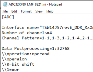
• Load the ini file: ADC32RF80_LMF_8821.ini

– Confirm yes to load firmware

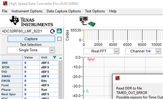
• Change to Complex FFT

• Change to Channel 1/8 - NOTE: This is not an option with the HSDC software connected to TSW14J57EVM as far as I can tell; Channel 1/4 is selected instead.

• Toggle the ADC Output Setup icon

– Click Enable? and Remember for this session

– Change the ADC Sampling rate to: 2949.12M

– Change the ADC Input Frequency to: 1960M

– Change NCO to: –1890M

– Change Decimation to: 12

– Press the OK button

• Press the Capture button

• Verify that LED D4 on TSW14J56 is blinking

• Verify tone capture in HSDC Pro similar to Figure 4

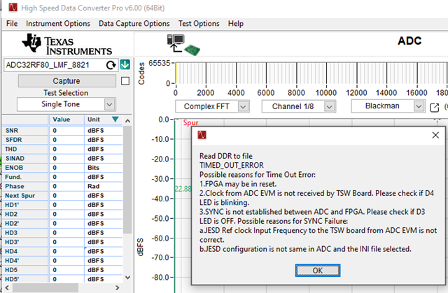
When I hit the "Capture" Button, I get this:

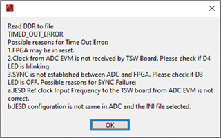
D4 LED is not blinking. LED status is: D1: ON; D2 OFF; D3 ON; D4 ON; D5 ON D6 off; D7 off; D8 ON; D9 ON.

Sometimes D3 has been off & as I was typing this D2 came on (with no prompts from me).

I've have seen D2 blink when using DAC, as I believe it should.

One additional item: I have only one available USB 3.0 on the computer I have so I have USB 3.0 connected to the TSW14J57EVM & USB 2.0 to the TSW40RF82 EVM.

Thanks for any help resolving this.

-Tom

  • Hi Tom,

    Can you share the screenshot of hsdc pro when the ini file is loaded? The ADC32RF80_LMF_8821 should have 8 channels regardless of viewing in Real FFT or in Complex FFT. If that is not correct then something is wrong with your file. Just wanted to confirm via screenshot.

    Thanks, Chase 

  • Yes, here it is.  I'm having a hard time adding a high-res screenshot of the whole HSDC but here's a partial view that has what I think are the important parts.

    -Tom

  • PS: Here's the .ini file - it should be unchanged from what was installed with the software.  I've looked at some of these files but not modified any.

  • I'm not sure that posted, here's a screenshot.  "Number of channels=4" looks interesting...

  • Thomas,

    This ini file is LMFS=8221, the adc is being configured for LMFS=8821 in the user guide. It is still weird that this shows 4 channels when M=2. Try with this ini file for 8821 mode. ADC32RF80_LMF_8821.ini

    Thanks, Chase

  • Chase, I just noticed the same .ini file selection issue that you noted and was writing up this update:

    As you noted, I had loaded:

    ADC32RF80_LMF_8221.ini,  rather than

    ADC32RF80_LMF_8821.ini.

    Now I have 8821 (the correct .ini file) per the instructions in the UG pasted above, but I still get the same error:

    LEDs:

    D4 LED is not blinking. LED status is: D1: ON; D2 blinking; D3 (see next line); D4 ON; D5 ON D6 off; D7 off; D8 ON; D9 ON.

    D3 appears to go between OFF & ON slowly on it's own (about a 17 second cycle time)

    The fact that D2 is blinking (which I think is correct for DAC mode) & D4 is not makes me think that somehow this is never getting sync'd to be in ADC mode.  What do you think?

    Thanks - Tom

  • OH, but the number of channels issue is resolved.  It's just the error message when I hit "Capture" that's the continuing problem.

    -Tom

  • Hi Tom,

    Can you share the register export?

    Also, a screenshot of these pages:

    • ADC32RFxx→ADC Configuration
    • ADC32RFxx→DDC Configuration
    • LMX2582
    • LMK04828→PLL1 Configuration
    • LMK04828→PLL2 Configuration
    • LMK04828→Clock Outputs

    Thanks, Chase

  • Chase,

    Yes - I assume that's done by "Low Level View / Save Configuration"

    Also an important update: 

    If I go thru the TSW40RF8x UG directions for DAC (4.1), play with section (5.2) DAC stuff, and then ADC (4.2), I can't get the ADC to work.

    HOWEVER, if I go thru the TSW40RF8x UG directions for DAC (4.1), and then directly to ADC (4.2), then the ADC to works as shown in the UG!  I.e., the only difference is whether I do or skip the section (5.2) DAC stuff before trying the ADC.

    So attached are 2 .cfg files - one "working" one "not working" case.
    8821_Not_working.cfg8821_working.cfg

    I'll gather the other things you asked for also, but it will be another day or so before I can work on that.

    Thanks.

    Tom

  • PS: this was only discovered today after I started using the correct .ini file as called for in the UG!  -Tom